Magnetic field generation method and synchrotron

A technology for synchrotrons and production methods, applied in the direction of magnetic resonance accelerators, accelerators, electrical components, etc., can solve problems such as prolonging the reset time of magnets and reducing the efficiency of synchrotrons

Active Publication Date: 2020-08-18
TSINGHUA UNIV
View PDF10 Cites 2 Cited by
  • Summary
  • Abstract
  • Description
  • Claims
  • Application Information

AI Technical Summary

Problems solved by technology

However, such a method also has to rise to the maximum magnetic field when the beam energy is l

Method used


Image

  • Magnetic field generation method and synchrotron
  • Magnetic field generation method and synchrotron
  • Magnetic field generation method and synchrotron

Examples


Embodiment Construction

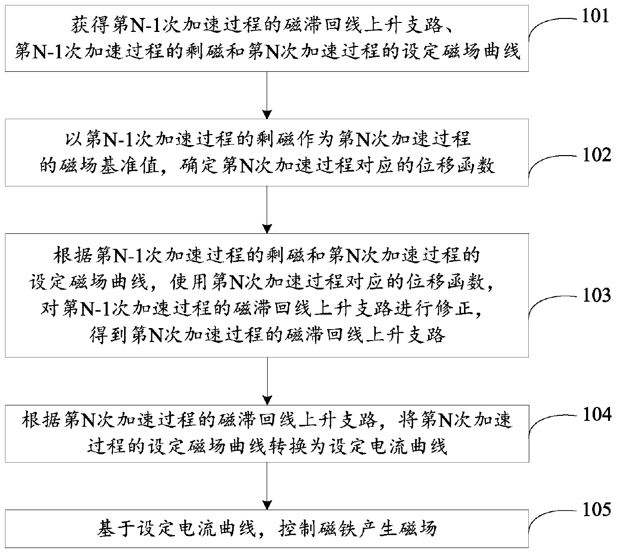
[0021] The technical solutions in the embodiments of the present application will be clearly and completely described below in conjunction with the drawings in the embodiments of the present application.

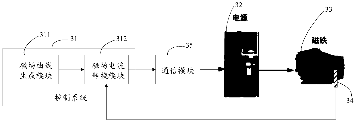
[0022] An embodiment of the present application provides a method for generating a magnetic field. In practical applications, the method for generating a magnetic field can be applied in a synchrotron, and the synchrotron includes: a magnet and a sensor for measuring residual magnetism arranged on the magnet.

[0023] In practical applications, the above-mentioned sensors for measuring remanence can be realized by sensors capable of measuring the magnitude of the magnetic field, such as a gauss meter (also called a Tesla meter), a remanence meter, a magnetometer, and a magnetic field strength measuring probe. Here, the embodiment of the present application does not make specific limitations.

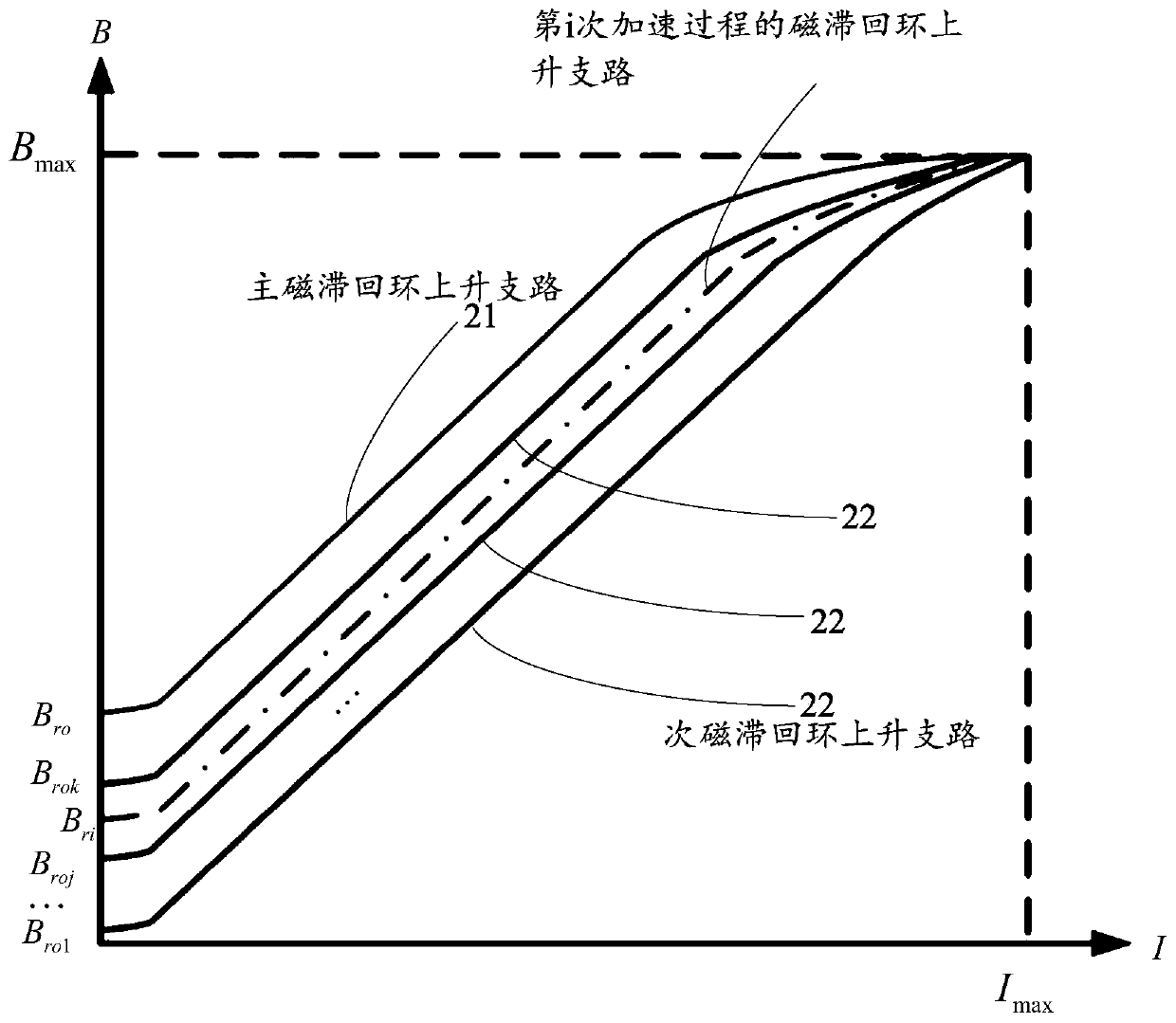
[0024] In the embodiment of the present application, the residual magnetization (...


PUM


Abstract

The embodiment of the invention provides a magnetic field generation method and a synchrotron. The magnetic field generation method comprises the steps of taking the residual magnetism of the (N-1)thacceleration process as a magnetic field reference value of the Nth acceleration process, and determining a displacement function corresponding to the Nth acceleration process, where N is a positive integer greater than 1; according to the residual magnetism of the (N-1)th acceleration process and a set magnetic field curve of the Nth acceleration process, correcting a hysteresis loop rising branch of the (N-1)th acceleration process by using a displacement function corresponding to the Nth acceleration process to obtain a hysteresis loop rising branch of the Nth acceleration process; converting the set magnetic field curve of the Nth acceleration process into a set current curve according to the hysteresis loop rising branch of the Nth acceleration process; and controlling the magnet to generate a magnetic field based on the set current curve. Therefore, hysteresis errors can be eliminated, the reset time of the magnet is shortened, and the efficiency of the synchrotron is improved.

Description

technical field [0001] The present application relates to the field of nuclear technology, in particular to a method for generating a magnetic field and a synchrotron. Background technique [0002] Synchrotron (Synchrotron) is a device that makes charged particles move along a fixed circular orbit in a high vacuum under the control of a magnetic field force, and is continuously accelerated (energy-lifted) by an electric field force to reach high energy. Many applications of synchrotrons require particle beams of different energies. For example, in clinical medicine, synchrotrons control the position of the Bragg peak in the human body by changing the energy of particle beams multiple times, so as to achieve accurate coverage of the lesion without damage. For the purpose of surrounding normal tissues, this requires the synchrotron to be able to precisely control the position and energy of the particle beam, which is currently mainly achieved by continuously changing different...

Claims


Application Information

Patent Timeline
IPC IPC(8): H05H13/04
CPCH05H13/04
Inventor 曾红锦郑曙昕姚红娟王学武
Owner TSINGHUA UNIV
Why Eureka
Try Eureka