A method and device for automatic welding of signs

An automatic welding and labeling technology, applied in the field of image processing, can solve problems such as reducing welding efficiency

Active Publication Date: 2020-10-09
JIANGSU JINHENG INFORMATION TECH CO LTD
View PDF7 Cites 0 Cited by
  • Summary
  • Abstract
  • Description
  • Claims
  • Application Information

AI Technical Summary

Problems solved by technology

[0005] In order to solve the problem of reducing the welding efficiency due to the need for image acquisition and image processing to obtain the coordinates of the welding points before welding each sign, this application discloses a method and device for automatic welding of signs through the following embodiments

Method used


Image

  • A method and device for automatic welding of signs
  • A method and device for automatic welding of signs
  • A method and device for automatic welding of signs

Examples


Embodiment Construction

[0077] In order to solve the problem of reducing welding efficiency because image acquisition and image processing are required to obtain the coordinates of welding points before welding each sign, the application discloses a method and device for automatically welding signs through the following embodiments.

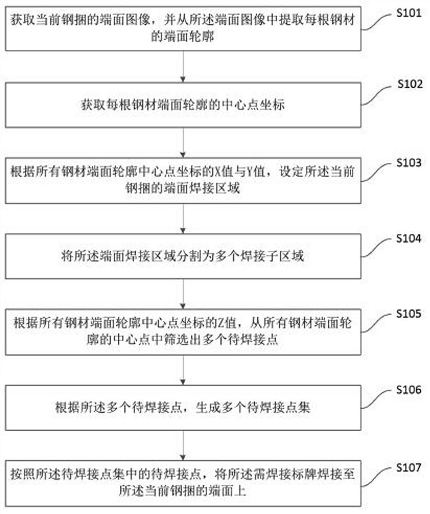
[0078] The first embodiment of the present application discloses a method for automatic welding of signs, see figure 1 As shown in the schematic diagram of the workflow, the method includes:

[0079] In step S101, the end face image of the current steel bundle is obtained, and the end face profile of each steel product is extracted from the end face image.

[0080] In one implementation, the end face image of the current steel bundle is collected by a binocular camera, the binocular camera includes a first camera and a second camera, and the collected end face image includes the first image collected by the first camera. An end face image and a second end face image co...


PUM


Abstract

This application relates to the field of image processing technology, and discloses a method and device for automatic welding of signs. The method includes: acquiring the end face image of the current steel bundle, extracting the end face profile of each steel and the coordinates of the center point of the end face profile, and setting The end face welding area of ​​the current steel bundle, and the end face welding area is divided into multiple welding sub-areas, multiple points to be welded are selected from the center points of all steel end face contours, and multiple sets of points to be welded are generated, each to be welded The number of points to be welded included in the point set is consistent with the number of welding sub-areas, and different points to be welded correspond to different welding sub-areas, and the distance between different points to be welded is not less than the size of the label to be welded, according to the number of points to be welded Concentrate the points to be welded for welding. In the above method, multiple sets of points to be welded are generated before welding, so that image acquisition and image processing do not need to be repeated during the welding process, which can save a lot of time and effectively improve welding efficiency.

Description

technical field [0001] The present application relates to the technical field of image processing, in particular to a method and device for automatic welding of signs. Background technique [0002] After bundling and packaging the steel, the steel factory usually welds a certain number of labels on the end face of each steel bundle. These labels are used to display the basic information of the steel bundle, such as model, specification and production date. The traditional sign welding method is manual welding, which has low efficiency and cannot be applied to large-volume production. In order to improve efficiency, many steel mills have generally adopted machine control to realize automatic welding of signs. [0003] The process of automatic welding sign generally includes: when the steel bundle is transported to the position to be welded, the system controls the binocular camera to collect the end face image of the steel bundle, through image processing, selects the first ...

Claims


Application Information

Patent Timeline
Patent Type & Authority Patents(China)
IPC IPC(8): B23K31/02B23K37/00G06T7/13G06T7/62
CPCB23K31/02B23K37/00G06T7/13G06T7/62
Inventor 孙茂杰李福存孙敬忠钱静洁朱正清周鼎苏循亮汪光明
Owner JIANGSU JINHENG INFORMATION TECH CO LTD
Why Eureka
Try Eureka