An inflatable ceramic inner wall printing device
An inflatable, ceramic technology, used in printing devices, printing, printing machines, etc., can solve problems such as poor printing effect and inability to meet printing work, and achieve the effect of meeting the requirements of different patterns and styles and improving printing efficiency.
- Summary
- Abstract
- Description
- Claims
- Application Information
AI Technical Summary
Problems solved by technology
Method used
Image
Examples
Embodiment 1
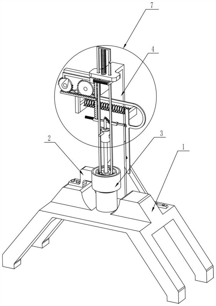
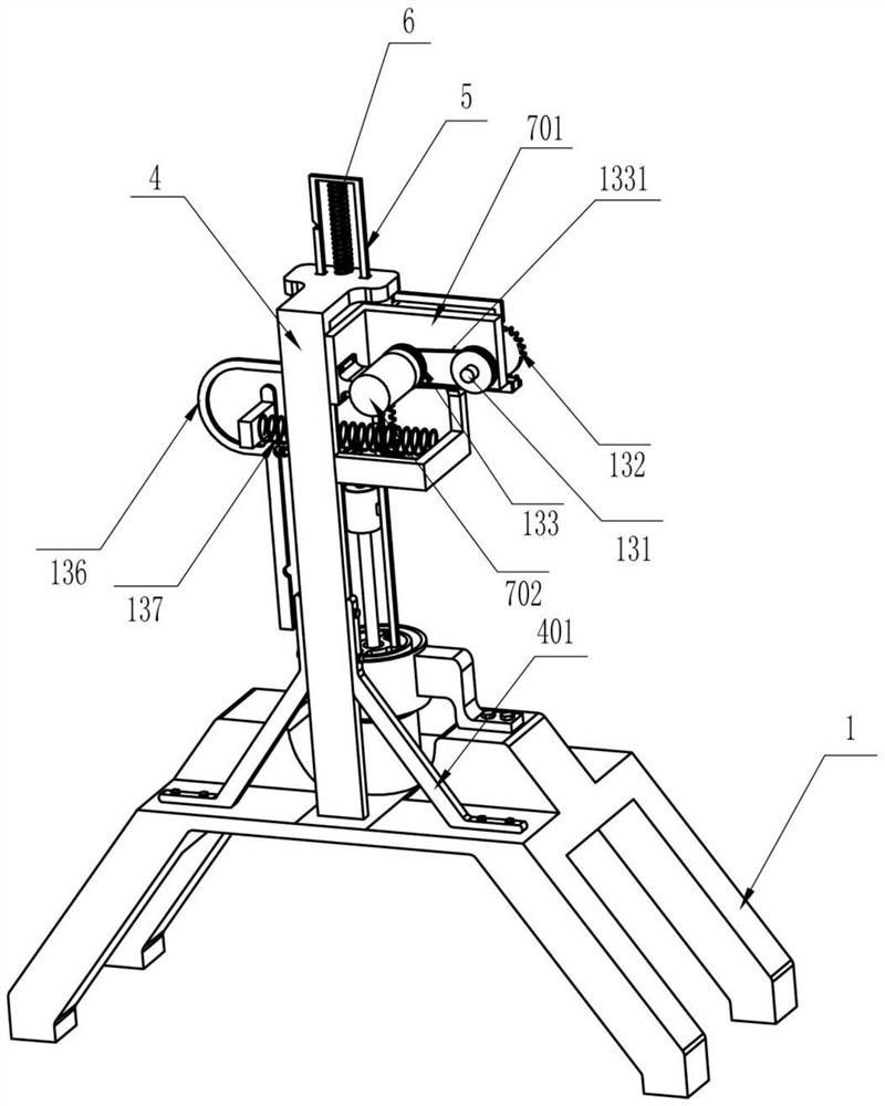
[0021] An inflatable ceramic inner wall printing device, such as Figure 1-6 As shown, it includes a support seat 1, a connecting seat 2, a sponge discharge disc 3, a fixed plate 4, a stable frame 401, a slide bar 5, a return spring 6, a hollow frame 8, a circular slide plate 9, and an icon plate 10. Staples 11, lifting parts 7, printing mechanism 12, transmission mechanism 13 and clamping mechanism 14, the left end of the connecting seat 2 that plays a connecting role is fixedly installed on the supporting seat 1, and the sponge used for placing printing pigments The discharge disc 3 is fixedly installed on the right end of the connection seat 2 and is located above the middle of the support seat 1. The lower end of the fixed plate 4 is fixedly installed on the support seat 1 and is located behind the sponge discharge disc 3. The two are used for stable fixing. The lower end of the stable frame 401 of the plate 4 is fixedly installed on the support base 1, the upper end is fi...
Embodiment 2
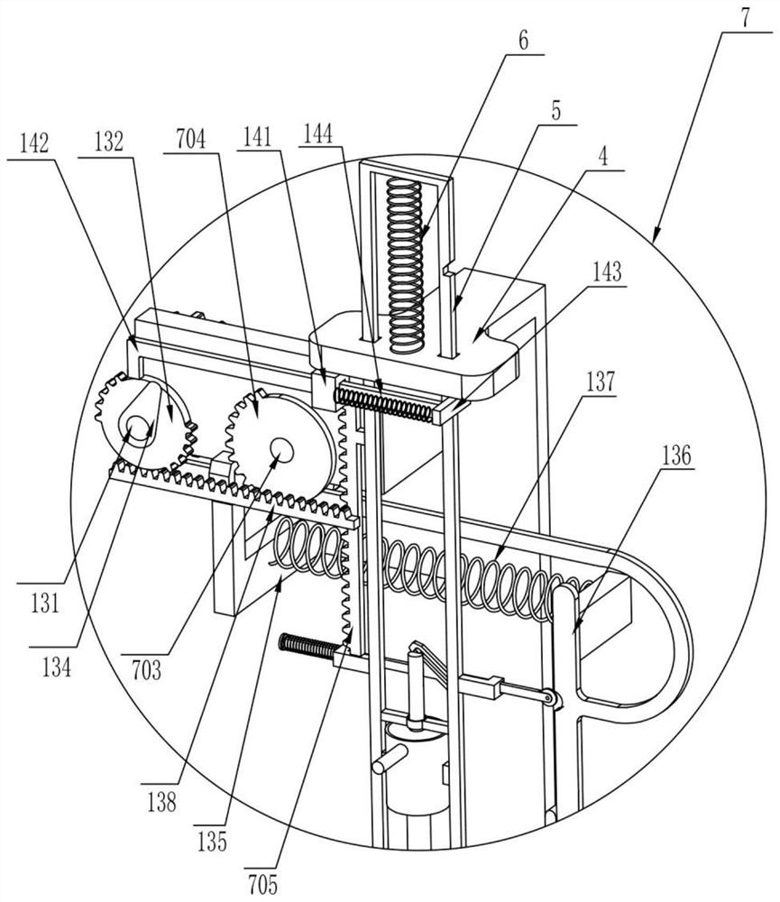
[0023] On the basis of Embodiment 1, such as Figure 1-6 As shown, the lifting part 7 that can make the slide bar one 5 and the printing mechanism 12 move downward includes a mounting plate 701, a drive motor 702, a transmission shaft 703, a sector gear 704 and a lifting rack 705, and the mounting plate 701 Fixedly installed on the left side of the fixed plate 4 and on the left side of the slide bar 5, the drive motor 702 is fixedly installed on the left side of the installed plate 701 and is close to the fixed plate 4, and the transmission shaft 703 that plays a transmission role is rotatably installed on the On the mounting plate 701 and the transmission shaft 703 passes through the mounting plate 701, while the rear end of the transmission shaft 703 is fixedly connected to the output end of the drive motor 702, the sector gear 704 is fixedly installed on the front end of the transmission shaft 703, and the lifting rack 705 is fixedly installed On the left side of slide bar ...
Embodiment 3
[0028] On the basis of Example 2, such as Figure 1-6 As shown, the transmission mechanism 13 includes a rotating shaft 131, a tooth-missing gear 132, a pulley 133, a belt 1331, a toggle lever 134, a pole 135, a push plate 136, a return spring 137 and a push rack 138. The rotating shaft 131 is rotatably installed on the mounting plate 701 and the rotating shaft 131 passes through the mounting plate 701. The tooth-missing gear 132 is fixedly mounted on the rotating shaft 131 and is located on the left side of the sector gear 704. The two pulleys 133 are fixedly installed on the Transmission shaft 703 and rotating shaft 131 rear ends and a pulley 133 are between the mounting plate 701 and the drive motor 702, the belt 1331 that plays a transmission role is wrapped around the two pulleys 133, and one end of the toggle lever 134 is fixedly installed on the The front end of the rotating shaft 131 is located in front of the toothless gear 132. The rear end of the pole 135 is fixedly...
PUM
 Abstract
Description
Claims
Application Information
 - R&D
- Intellectual Property
- Life Sciences
- Materials
- Tech Scout
- Unparalleled Data Quality
- Higher Quality Content
- 60% Fewer Hallucinations
Browse by: Latest US Patents, China's latest patents, Technical Efficacy Thesaurus, Application Domain, Technology Topic, Popular Technical Reports.
© 2025 PatSnap. All rights reserved.Legal|Privacy policy|Modern Slavery Act Transparency Statement|Sitemap|About US| Contact US: help@patsnap.com


