Inflatable ceramic inner wall printing device

An inflatable and ceramic technology, applied in printing devices, printing, printing machines, etc., can solve the problems of poor printing effect and unsatisfactory printing work, meet the requirements of different patterns and styles, and improve printing efficiency.

Active Publication Date: 2020-08-21
YELLOW RIVER CONSERVANCY TECHN INST
View PDF10 Cites 6 Cited by
  • Summary
  • Abstract
  • Description
  • Claims
  • Application Information

AI Technical Summary

Problems solved by technology

[0003] In order to overcome the shortcomings that the existing ceramic printing molds cannot meet the printing work on the inner walls of different types of ceramics and the printing effect is poor, the technical problem of the present invention is to provide a method that can print the inner walls of different types of ceramics and make the pigment printing uniform, ensuring Inflatable ceramic inner wall printing device with printing effect

Method used


Image

  • Inflatable ceramic inner wall printing device
  • Inflatable ceramic inner wall printing device
  • Inflatable ceramic inner wall printing device

Examples


Embodiment 1

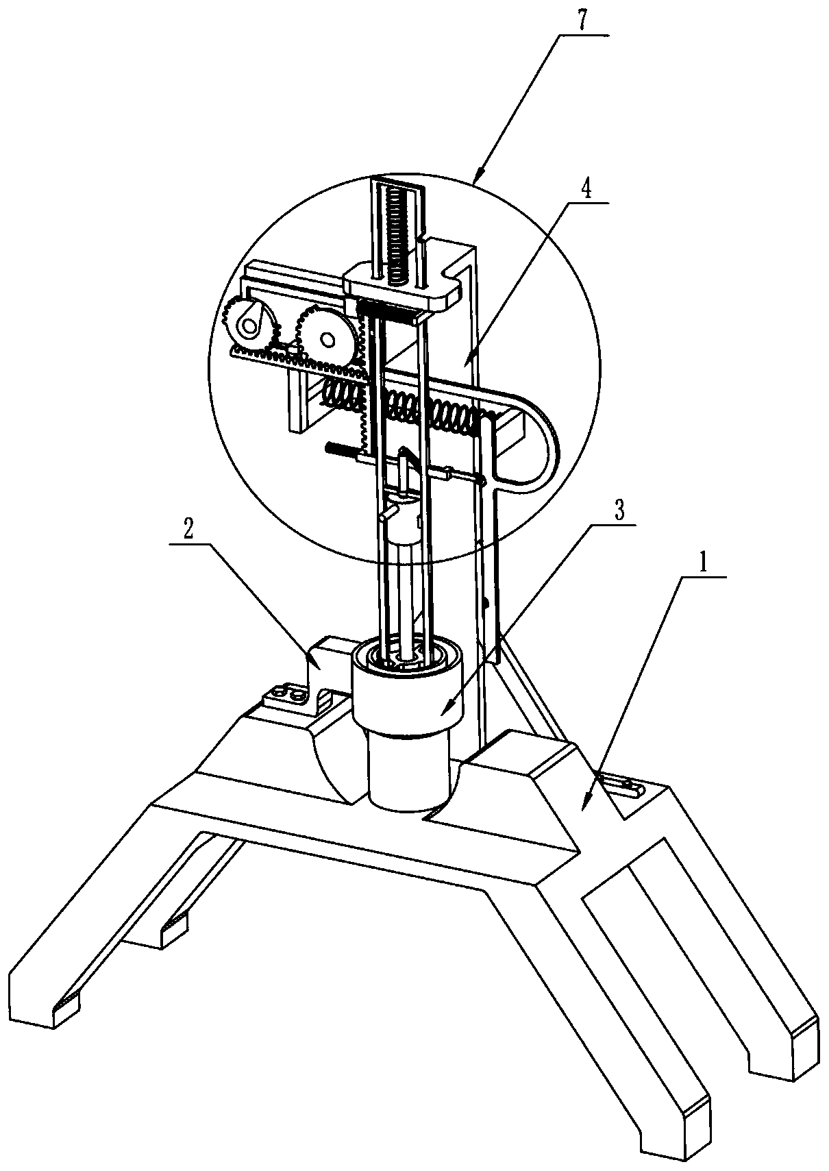
[0021] An inflatable ceramic inner wall printing device, such as Figure 1-6 As shown, it includes a support seat 1, a connecting seat 2, a sponge discharge disc 3, a fixed plate 4, a stable frame 401, a slide bar 5, a return spring 6, a hollow frame 8, a circular slide plate 9, and an icon plate 10. Staples 11, lifting parts 7, printing mechanism 12, transmission mechanism 13 and clamping mechanism 14, the left end of the connecting seat 2 that plays a connecting role is fixedly installed on the supporting seat 1, and the sponge used for placing printing pigments The discharge disc 3 is fixedly installed on the right end of the connection seat 2 and is located above the middle of the support seat 1. The lower end of the fixed plate 4 is fixedly installed on the support seat 1 and is located behind the sponge discharge disc 3. The two are used for stable fixing. The lower end of the stable frame 401 of the plate 4 is fixedly installed on the support base 1, the upper end is fi...

Embodiment 2

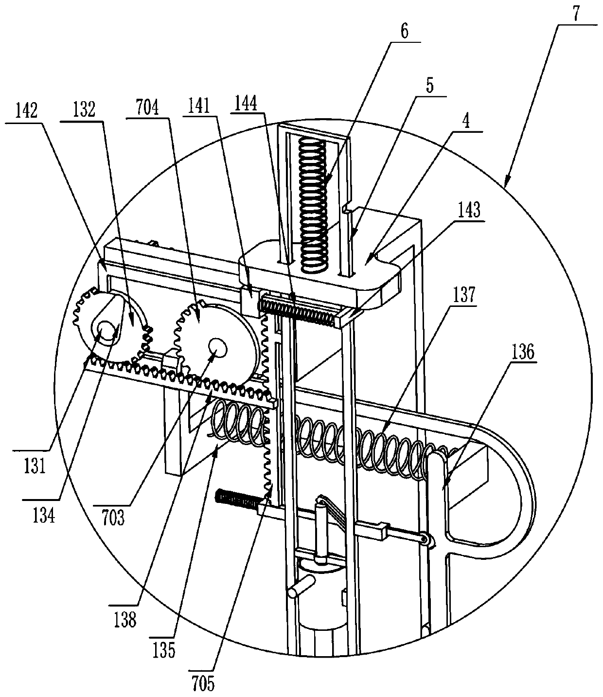
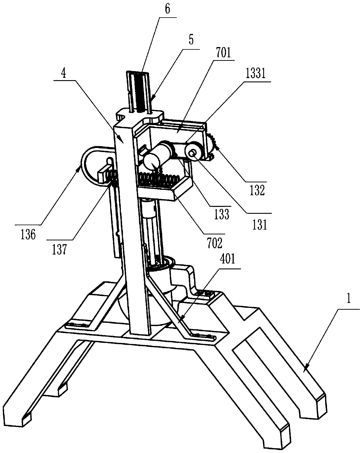
[0023] On the basis of Embodiment 1, such as Figure 1-6 As shown, the lifting part 7 that can make the slide bar one 5 and the printing mechanism 12 move downward includes a mounting plate 701, a drive motor 702, a transmission shaft 703, a sector gear 704 and a lifting rack 705, and the mounting plate 701 Fixedly installed on the left side of the fixed plate 4 and on the left side of the slide bar 5, the drive motor 702 is fixedly installed on the left side of the installed plate 701 and is close to the fixed plate 4, and the transmission shaft 703 that plays a transmission role is rotatably installed on the On the mounting plate 701 and the transmission shaft 703 passes through the mounting plate 701, while the rear end of the transmission shaft 703 is fixedly connected to the output end of the drive motor 702, the sector gear 704 is fixedly installed on the front end of the transmission shaft 703, and the lifting rack 705 is fixedly installed On the left side of slide bar ...

Embodiment 3

[0028] On the basis of Example 2, such as Figure 1-6 As shown, the transmission mechanism 13 includes a rotating shaft 131, a tooth-missing gear 132, a pulley 133, a belt 1331, a toggle lever 134, a pole 135, a push plate 136, a return spring 137 and a push rack 138. The rotating shaft 131 is rotatably installed on the mounting plate 701 and the rotating shaft 131 passes through the mounting plate 701. The tooth-missing gear 132 is fixedly mounted on the rotating shaft 131 and is located on the left side of the sector gear 704. The two pulleys 133 are fixedly installed on the Transmission shaft 703 and rotating shaft 131 rear ends and a pulley 133 are between the mounting plate 701 and the drive motor 702, the belt 1331 that plays a transmission role is wrapped around the two pulleys 133, and one end of the toggle lever 134 is fixedly installed on the The front end of the rotating shaft 131 is located in front of the toothless gear 132. The rear end of the pole 135 is fixedly...


PUM


Abstract

The invention relates to the technical field of ceramic printing, in particular to an inflatable ceramic inner wall printing device which is provided for achieving the technical effects of being capable of printing patterns on the inner walls of different types of ceramics, uniform in pigment printing and capable of ensuring the printing effect. According to the technology implementation scheme, the inflatable ceramic inner wall printing device comprises a supporting base, a connecting seat, a sponge storage disk, a fixed plate, stabilizing supports, a sliding rod I, a return spring I, a hollow frame, a circular sliding plate, a pattern plate, clamp nails and the like. One end of the connecting seat is fixedly mounted on the supporting base. The sponge storage disk is fixedly mounted at the other end of the connecting seat. One end of the fixed plate is fixedly mounted on the supporting base. The inflatable ceramic inner wall printing device is provided with a printing mechanism and alifting component, can automatically inflate air into a dyeing airbag to expand, be stained with pigment and move into ceramic to conduct uniform printing on the inner wall of the ceramic, and ensuresthe ceramic inner wall printing effect while improving the printing efficiency.

Description

technical field [0001] The invention relates to the technical field of ceramic printing, in particular to an inflatable ceramic inner wall printing device. Background technique [0002] Printing decoration is one of the traditional decoration methods of ceramics in our country. Color materials are printed on ceramic products, and then put into earthen kilns to be fired into shapes, with rich layers and strong three-dimensional effect. The traditional printing method is to emboss concave-convex patterns on the surface of the green body with a stamping tool with patterns, and then glaze and fire. This method of embossing patterns now uses pressure and embossing to make convex or concave patterns on the inner wall of the plaster model. When the mud is put into molding, concave or convex patterns appear on the outside of the body. , fired after trimming and glazing. However, the traditional stamping tools cannot meet the printing requirements for the inner wall of ceramics of ...

Claims


Application Information

Patent Timeline
Patent Type & Authority Applications(China)
IPC IPC(8): B41F17/00B41F27/14B41F31/02
CPCB41F17/32B41F27/14B41F31/02B41P2217/10B41P2217/50
Inventor 余文霞
Owner YELLOW RIVER CONSERVANCY TECHN INST
Why Eureka
Try Eureka