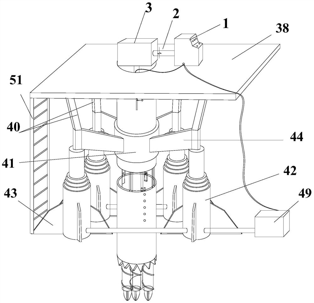
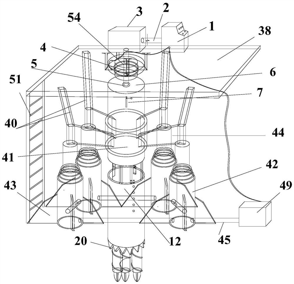
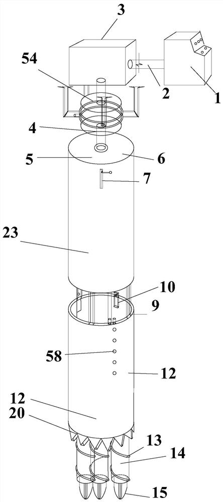
A multi-head soil dumper drill bit in hard soil area

A multi-head drill and soil dumper technology, which is used in drill bits, earth-moving drilling, drilling equipment, etc., can solve the problems of soil hole collapse, difficulty in crushing soil discharge, large drill bit loss, etc., and achieves convenient disassembly and installation. Reliable, faster construction results

Active Publication Date: 2022-02-01
HEBEI INSTITUTE OF ARCHITECTURE AND CIVIL ENGINEERING
View PDF6 Cites 0 Cited by
  • Summary
  • Abstract
  • Description
  • Claims
  • Application Information

AI Technical Summary

Problems solved by technology

[0003] At present, the main equipment used in drilling technology is a single drill bit. This kind of drill bit has limited ability to drill soil in hard soil areas, and the loss of the drill bit itself is great; Discharge will cause the soil hole to collapse due to the splashing of broken soil when drilling the soil. The main problems are as follows:
[0004] 1. The drill bit is single, it is difficult to ensure the stability of the soil, resulting in the final collapse of the soil hole
[0005] 2. For hard soil areas, it is difficult to perform drilling operations with a single drill bit, and the loss of the drill bit is too large to reach a fixed depth
[0006] 3. During the drilling process, there are no protective measures for the soil holes, and the soil holes are uneven, resulting in a large waste of materials in the project
[0007] 4. After drilling, the soil in the hole is difficult to discharge, and it is difficult to guarantee the quality of the project due to excessive residue during pouring
[0008] On the one hand, the above-mentioned problems mainly affect the construction quality of the project; on the other hand, for the construction period, if there are too many drilling errors and delay the construction period, it will also have a certain impact on the project cost, and the loss of the drill bit itself is great; and When the ordinary drill bit is drilling soil, it is difficult to discharge the broken soil in the air, which will lead to the collapse of the soil hole due to the splashing of the broken soil when drilling the soil.

Method used


Image

  • A multi-head soil dumper drill bit in hard soil area
  • A multi-head soil dumper drill bit in hard soil area
  • A multi-head soil dumper drill bit in hard soil area

Examples


Embodiment Construction

[0038] It should be noted that the features of the present invention in the present invention may be combined with each other in the case of an unable conflict.

[0039] In the description of the present invention, it is to be understood that the terms "center", "longitudinal", "horizontal", "upper", "lower", "front", "post", "left", "right", " The orientation relationship between the orientation of the indicated by the vertical "," horizontal "," top "," bottom "," inside "," outer ", etc. is based on the orientation or positional relationship shown in the drawings, is merely described in the present invention and Simplify the description, rather than indicating or implying that the device or element must have a specific orientation, constructed and operated in a particular direction, and thus is not to be construed as limiting the invention. Moreover, the terms "first", "second", etc. are only used to describe purposes, and cannot be understood as an indication or implies relati...


PUM


Abstract

The invention provides a drill bit for a multi-head soil dumper in a hard soil area, which includes a longitudinal transmission rod, an upper sleeve, several lower sleeves, a drill assembly, an electromagnetic exciter, and a lifting platform. The drill assembly is located at the The outer side of the longitudinal transmission rod, and cooperate with the longitudinal transmission rod, the upper sleeve is sleeved on the outer side of the longitudinal transmission rod, and the lower sleeve is connected with each other, and is sleeved on the The outer side of the drill bit assembly, the electromagnetic exciter is fixed on the longitudinal transmission rod, and is located above the upper sleeve, and the upper sleeve is fixed on the lifting platform. The drill bit of the multi-head soil dumper in the hard soil area of ​​the present invention can be lifted and lowered, which facilitates the disassembly and installation of various structures and avoids the difficulty of device disassembly. At the same time, the operating platform can simultaneously control the lifting of the platform and the drilling of the drill bit, reducing personnel and operations. Simple.

Description

Technical field [0001] The present invention belongs to the field of drill and soil, in particular, involving a hard soil region of multi-headed drilling and row soil. Background technique [0002] Drilling technology is a commonly used construction technology for the use of civil engineering and the survey project. The technology needs to carry out drilling of soil through various instruments, while other operations, such as drilling piles, drilling exploration, etc., can greatly improve work efficiency by drilling, exploration can early warning applicability. Engineering staff can greatly increase construction convenience and safety. [0003] At present, the main application of the drilling technology is a single drill bit. This drill bit is limited to the hard soil region of the hard soil region, and the loss of the drill bits itself; and the ordinary drill bit is breasted, it is difficult to take the earth. Exhausted, caused by the splash of the earth to collapse due to the s...

Claims


Application Information

Patent Timeline
Patent Type & Authority Patents(China)
IPC IPC(8): E21B10/44E21B10/36E21B10/43E21B10/62E21B21/015E21B33/13E21B7/24B66F7/20B66F7/28
CPCE21B10/445E21B10/43E21B10/62E21B21/015E21B33/13E21B7/24B66F7/20B66F7/28
Inventor 郁雯刘杰薛晓峰李凯尚康君
Owner HEBEI INSTITUTE OF ARCHITECTURE AND CIVIL ENGINEERING
Why Eureka
Try Eureka