Balanced type air-driven hydraulic pump

A pneumatic-hydraulic pump, balanced technology, applied in the field of hydraulic pumps, can solve the problems of easy frosting and freezing of compressed gas, small flow rate, difficult pump aerodynamics, etc., and achieve the effect of quick ventilation, high working efficiency and compact structure

Pending Publication Date: 2020-08-21
滁州吉玻液压系统技术有限公司
View PDF0 Cites 3 Cited by
  • Summary
  • Abstract
  • Description
  • Claims
  • Application Information

AI Technical Summary

Problems solved by technology

However, the pump is powered by compressed gas, and the compressed gas is prone to frost and ice under extremely cold conditions, which makes the pump difficult to operate
And the flow is small, only suitable for working under high pressure and small flow requirements

Method used


Image

  • Balanced type air-driven hydraulic pump
  • Balanced type air-driven hydraulic pump
  • Balanced type air-driven hydraulic pump

Examples


Embodiment 1

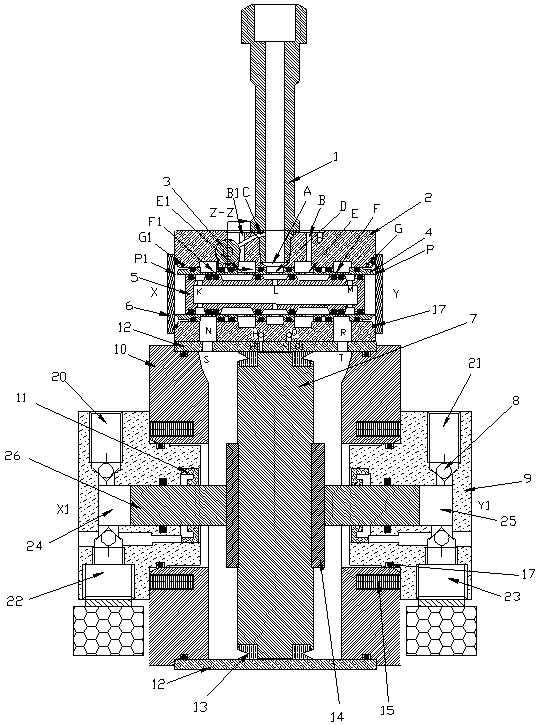
[0022] Embodiment 1: as Figure 1-9 Shown: a balanced pneumatic hydraulic pump, characterized in that it includes a plunger body 9, an end cover body 10, a piston barrel 12, a piston 7 arranged in the piston barrel, a piston linkage shaft 26, and a top set of the piston barrel 12. There is a reversing valve body 2 reversing control mechanism, and the reversing valve control mechanism includes: a compressed gas inlet pipe 1 connected to the reversing valve body, a long slide shaft 5 arranged in the chamber of the reversing valve body 2, and a The copper sleeve 4 in the chamber of the long sliding shaft 5 and the reversing valve body 2, the short sliding shaft 3 in the reversing valve body 2, and the plugs 18 at both ends of the short sliding shaft 3 are arranged in the reversing valve body 2 the external baffle plate 6, the lower left side of the reversing valve body 2 is provided with an inner vent hole N, and the inner vent hole N is connected with the piston barrel vent hole...

Embodiment 2

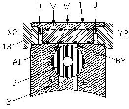
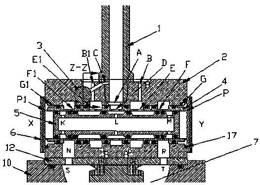
[0028] Embodiment 2: as Figure 4-6 Shown: a working method of a balanced pneumatic hydraulic pump: compressed gas passes through the C hole of the intake pipe 1 → enters the third built-in air intake W of the reversing valve body 2 → at this time, if the short slide shaft 3 is stressed to Y2 Direction movement, when moving to the seventh built-in air port B2 of the reversing valve body → enter the left air port G1 of the reversing valve body → enter the P1 port on the left end of the copper sleeve 4, at this time the compressed gas pushes the long sliding shaft in the copper sleeve 4 The end of 5 moves in the Y direction. When the long sliding shaft 5 moves to the air port F1 of the copper sleeve in the copper sleeve 4, the compressed gas passes through the intake pipe 1 → enters the air inlet A of the reversing valve body → enters the copper sleeve in the reversing valve body Air inlet D → enter the air inlet L in the middle of the long sliding shaft 5 → due to the limitatio...

Embodiment 3

[0030] Embodiment 3: as Figure 7-9 Shown: Another working method of balanced air-hydraulic pump: Compressed gas passes through the C hole of the intake pipe 1 → enters the built-in third air intake W of the reversing valve body 2 → at this time, if the short slide shaft 3 is forced toward Move in the X2 direction, when moving to the air port A1 → enter the lower air port G on the right side of the reversing valve body 2 → pass through the P port on the right end of the copper sleeve 4, at this time the compressed gas pushes the long sliding shaft 5 in the copper sleeve 4 to the end face Moving in the X direction, when the long sliding shaft 5 moves to the air port F of the copper sleeve 4 in the copper sleeve 4, the compressed gas passes through the intake pipe 1 → enters the air inlet A of the reversing valve body → enters the copper sleeve in the reversing valve body 4 Air inlet D → enter the air inlet L in the middle of the long sliding shaft 5 → due to the limitation of t...


PUM


Abstract

The invention relates to a balanced type air-driven hydraulic pump which is characterized by comprising a plunger body, an end cover body, a piston barrel, a piston arranged in the piston barrel and apiston linkage rod, wherein the top of the piston barrel is connected with a reversing valve body. A reversing valve body control mechanism comprises an air inlet pipe connected with the reversing valve body, a long sliding shaft arranged in a chamber of the reversing valve body, a copper bush arranged between the long sliding shaft and the chamber of the reversing valve body, a short sliding shaft arranged in the reversing valve body, plugs at the two ends of the short sliding shaft and a baffle plate arranged at the outer part of the reversing valve body. An vent hole is formed in the lowerpart of the reversing valve body and is connected with the top end of the piston barrel. The balanced type air-driven hydraulic pump has the advantages of compact structure and small volume and can realize the output of high pressure value. Meanwhile, the air-driven hydraulic pump also has the advantages of good air exchange tightness, simple reversing air path, quick air exchange and high working efficiency.

Description

technical field [0001] The invention relates to a hydraulic pump, in particular to a balanced pneumatic hydraulic pump. Background technique [0002] The hydraulic pump is powered by a motor or an oil engine, and has a large volume, a large flow rate, and a low pressure. Moreover, sparks are generated, so it cannot be used in flammable and explosive places, and requires manual control, which is cumbersome to operate. The balanced air-hydraulic pump is driven by compressed gas, with small volume and high pressure, up to 1000bar. The operation is simple. When the set hydraulic pressure is reached, the pump will stop automatically, and when the set pressure is lower than the set pressure, the pump will automatically start without human manipulation. Moreover, there is no spark, and it can be used in flammable and explosive places. But the pump is driven by compressed gas, and the compressed gas is easy to frost and freeze under extremely cold conditions, which makes the pump...

Claims


Application Information

Patent Timeline
Patent Type & Authority Applications(China)
IPC IPC(8): F04B9/123F04B49/22F04B53/14
CPCF04B9/123F04B49/22F04B53/14F04B53/143F04B53/145
Inventor 周剑培
Owner 滁州吉玻液压系统技术有限公司
Why Eureka
Try Eureka