An automatic painting device for steel pipes

An automatic, steel pipe technology, applied to the surface coating liquid device, transportation and packaging, conveyor objects, etc., can solve the problem of manpower consumption, and achieve the effect of simple operation and labor saving

Active Publication Date: 2022-02-01
DEXIN STEEL PIPE CHINA
View PDF1 Cites 0 Cited by
  • Summary
  • Abstract
  • Description
  • Claims
  • Application Information

AI Technical Summary

Problems solved by technology

[0006] In order to overcome the disadvantages of the above-mentioned patents that the steel pipes need to be placed and taken out manually, and the operation is relatively labor-intensive, the technical problem to be solved by the invention is to provide a kind of operation that does not require frequent placing and taking out of the steel pipes manually, and can be used during operation. Manpower-saving steel pipe automatic painting device

Method used


Image

  • An automatic painting device for steel pipes
  • An automatic painting device for steel pipes
  • An automatic painting device for steel pipes

Examples


Embodiment 1

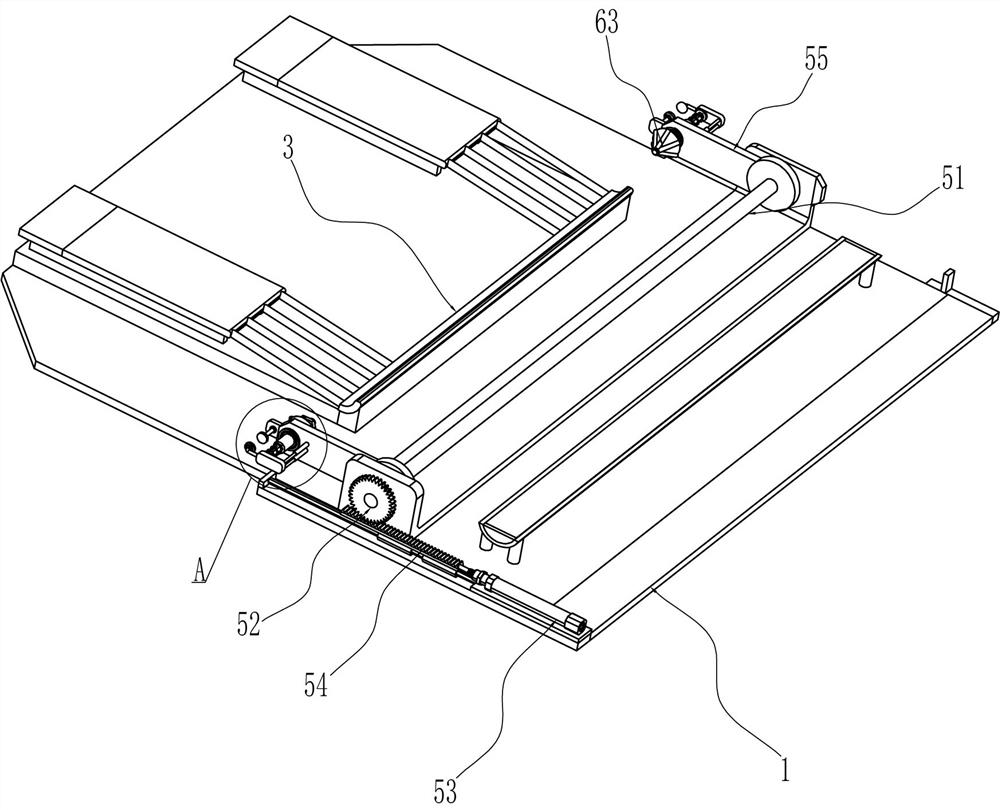
[0028] A steel pipe automatic painting device, such as Figure 1-3 As shown, it includes a base 1, a discharge ramp 2, an arc-shaped baffle 3 and a liquid storage frame 4. The rear side of the top of the base 1 is connected to a discharge ramp 2, and the front side of the discharge ramp 2 is connected to an arc-shaped stop. The plate 3 is connected to the liquid storage frame 4 on the front side of the top of the base 1, and also includes a driving assembly 5 and a clamping assembly 6. The base 1 is provided with the driving assembly 5, and the driving assembly 5 is provided with the clamping assembly 6.

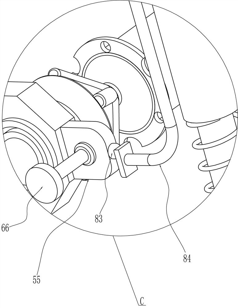
[0029] The driving assembly 5 includes a first rotating shaft 51, a driving gear 52, a cylinder 53, a driving rack 54 and a mounting plate 55. The top of the base 1 on the rear side of the liquid storage frame 4 is rotatably connected to the first rotating shaft 51, and the left end of the first rotating shaft 51 A driving gear 52 is connected, a cylinder 53 is installed on ...

Embodiment 2

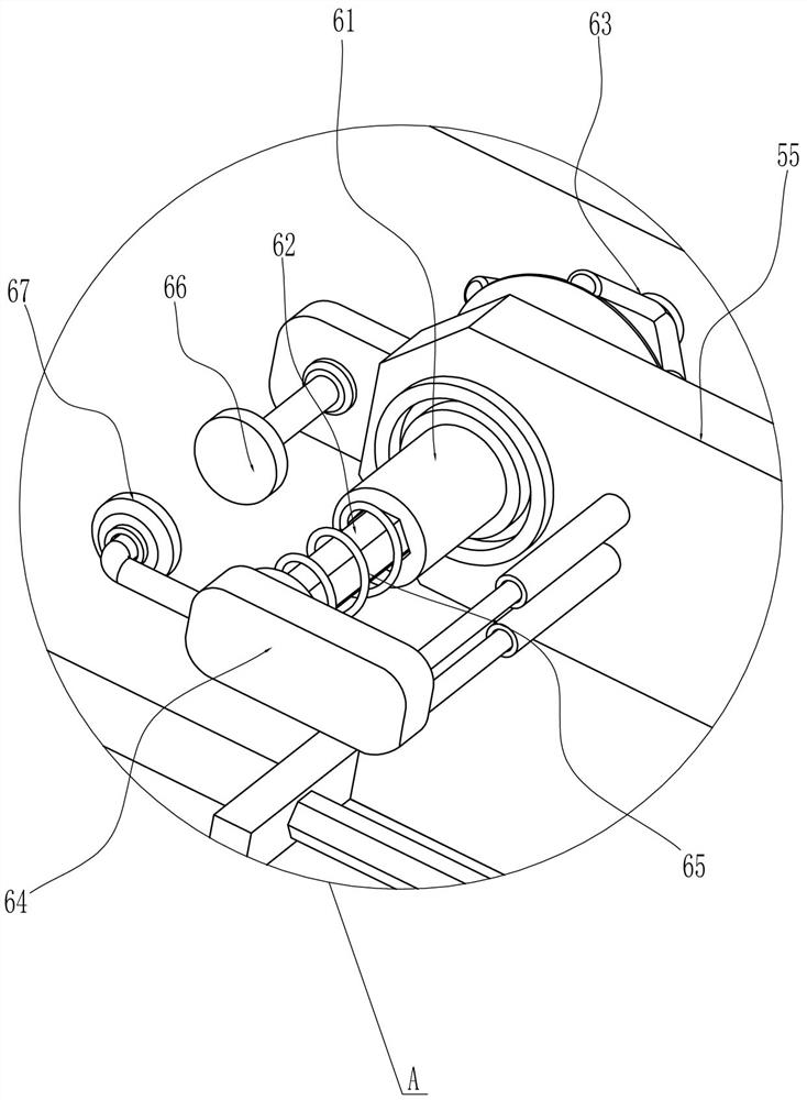
[0033] On the basis of Example 1, such as Figure 4-5 As shown, a rotating assembly 7 is also included, and the rotating assembly 7 includes a sector gear 71, a transmission gear 72, a transmission rack 73, a return spring 74, a second rotating shaft 75, a one-way clutch 76, a first cylindrical gear 77 and a second Cylindrical gear 78, sector gear 71 is connected to the right end of the first rotating shaft 51, transmission gear 72 is connected on the inner rhombic casing 61 on the right side, and transmission rack 73 is slidingly connected to the right side of the top of base 1, transmission gear 72 will be connected with transmission The gear rack 73 is meshed, and the transmission rack 73 is connected with the back spring 74 between the base 1. The right side of the base 1 is rotatably connected with the second rotating shaft 75, and the second rotating shaft 75 is connected with a one-way clutch 76. On the one-way clutch 76 A first cylindrical gear 77 is connected, and the...


PUM


Abstract

The invention relates to a painting device, in particular to an automatic painting device for steel pipes. The technical problem to be solved by the present invention is to provide an automatic painting device for steel pipes that does not require frequent manual placement and removal of steel pipes and can save manpower during operation. In order to solve the above-mentioned technical problems, the present invention provides such an automatic painting device for steel pipes, which includes: a base, which is connected to the top side of the base, and an arc-shaped baffle is connected to the discharge ramp; a liquid storage frame, which is connected to On the other side of the top of the base; the driving assembly is arranged on the base. The invention can put the steel pipe into the paint bucket through the cooperative operation of the driving component and the clamping component, and then rotate the steel pipe to complete the dyeing, so that the effect of dyeing the steel pipe can be achieved.

Description

technical field [0001] The invention relates to a painting device, in particular to an automatic painting device for steel pipes. Background technique [0002] A steel pipe is a steel material with a hollow section whose length is much greater than its diameter or circumference. According to the cross-sectional shape, it can be divided into circular, square, rectangular and special-shaped steel pipes; according to the material, it can be divided into carbon structural steel pipes, low alloy structural steel pipes, alloy steel pipes and composite steel pipes; Steel pipes for thermal equipment, petrochemical industry, machinery manufacturing, geological drilling, high pressure equipment, etc. After some steel pipes are manufactured, the steel pipes need to be painted. [0003] After retrieval, the authorized patent publication number is CN205887299U, which discloses a painting device for iron pipes, especially relates to a high-efficiency painting device for iron pipes. The...

Claims


Application Information

Patent Timeline
Patent Type & Authority Patents(China)
IPC IPC(8): B05C3/04B05C3/10B05C13/02B65G47/82
CPCB05C3/04B05C3/10B05C13/02B65G47/82
Inventor 万嘉颖
Owner DEXIN STEEL PIPE CHINA
Why Eureka
Try Eureka