Multi-face washing equipment for broken glass for glass production

A technology for broken glass and glass, which is applied in the field of multi-faceted glass washing equipment for glass production, can solve the problems of failing to meet the sanitary standards of broken glass, incomplete washing, and sticking impurities, etc. the effect of causing damage

Active Publication Date: 2020-08-25
SUZHOU YUQIAN INFORMATION TECH CO LTD
View PDF10 Cites 5 Cited by
  • Summary
  • Abstract
  • Description
  • Claims
  • Application Information

AI Technical Summary

Problems solved by technology

[0005] The object of the present invention is to provide a multi-faceted cullet washing equipment for glass making, to solve the problem of manually washing a large amount of cullets in the above background technology, which is inefficient and incomplete, resulting in the surface of the cullets still sticking. There are some impurities, which cannot meet the hygienic standard of secondary recycling of broken glass

Method used


Image

  • Multi-face washing equipment for broken glass for glass production
  • Multi-face washing equipment for broken glass for glass production
  • Multi-face washing equipment for broken glass for glass production

Examples


Embodiment 1

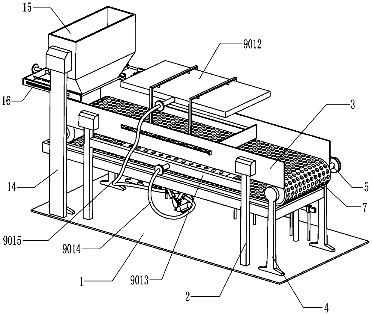
[0024] A multi-faceted washing equipment for cullet for glass making, such as Figure 1-6As shown, it includes a bottom plate 1, a support plate 2, a limit plate 3, a support seat 4, a first transmission roller 5, a second transmission roller 6, a mesh conveyor belt 7, a cullet flattening device 8, a servo motor 803, The first rotating shaft 804, the water spray direction adjusting device 9, the small diameter gear 10, the large diameter gear 11, the first pulley 12, the first flat belt 13, the top plate 14, the discharge frame 15, the guide frame 16, the material retaining plate 17 and The second compression spring 18, three supporting plates 2 are fixedly installed on the upper side of the base plate 1, and two limiting plates 3 arranged in parallel are fixedly installed on the upper ends of the three supporting plates 2, and both limiting plates 3 are There is a chute, and two sets of support bases 4 are fixedly installed on the left and right ends of the upper side of the ...

Embodiment 2

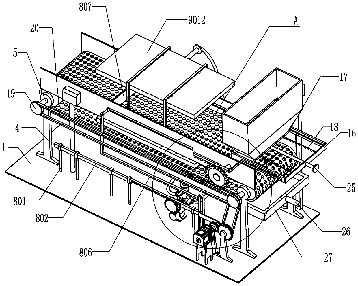
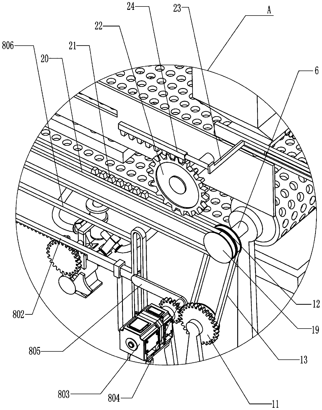
[0031] On the basis of Example 1, as Figure 2-3 As shown, it also includes a second pulley 19, a second flat belt 20, a tooth block 21, a second drive gear 22, a connecting rod 23 and a rack 24, one end of the first drive roller 5 and the second drive roller 6 A second pulley 19 is installed at the rear end of the second pulley, and a second flat belt 20 is connected between the two second pulleys 19. Seven tooth blocks 21 are installed on the second flat belt 20, and the second drive gear 22 is installed on the rear side of one of the limiting plates 3 through a rotating shaft and meshes with seven tooth blocks 21. The connecting rod 23 is fixedly installed on the material blocking plate 17 and is in sliding contact with the guide frame 16. The rack 24 It is fixedly installed on the right end of the connecting rod 23 and meshes with the second driving gear 22 .

[0032] In specific use, the clockwise rotation of the second drive roller 6 will drive one of the second pulleys...

Embodiment 3

[0034] On the basis of Example 2, such as figure 2 As shown, a pull rod 25 is also included. The pull rod 25 is fixedly installed on the left side of the material baffle 17 and passes through the guide frame 16. The function of the pull rod 25 is convenient for the staff to manually pull the material baffle 17 when necessary. move.

[0035] Such as figure 2 As shown, it also includes a drain pipe 26 and a liquid collection plate 27. The liquid collection plate 27 used to collect the waste water generated by the washing operation of broken glass is fixedly installed on two sets of support bases 4, and the liquid collection plate 27 is positioned at the below of network port conveyer belt 7, and the left part of described liquid collecting plate 27 offers a round hole and is equipped with drain pipe 26 in the round hole, and described drain pipe 26 is used for collecting the liquid collected by liquid collecting plate 27. Waste water is discharged.

[0036]In specific use, ...


PUM


Abstract

The invention relates to the technical field of glass processing, in particular to multi-face washing equipment for broken glass for glass production. The multi-face washing equipment for the broken glass for the glass production can spread and disperse the broken glass before washing a large amount of the broken glass, so that each piece of the broken glass can be washed, the upper and lower sides of the broken glass can be washed, and the recycled broken glass can better meet the secondary recycling sanitary standard. According to the technical scheme, the multi-face washing equipment for the broken glass for the glass production comprises a bottom plate, support plates, a limit plate, a support seat, a first transmission roller, a second transmission roller, a mesh conveyor belt and thelike. A plurality of supporting plates are fixedly installed on one side of the bottom plate. Broken glass piles on the mesh conveyor belt can firstly be spread and dispersed, so that each piece of the broken glass can be washed, and the upper and lower sides of the broken glass can be washed completely and thoroughly.

Description

technical field [0001] The invention relates to the technical field of glass processing, in particular to multi-faceted washing equipment for broken glass used in glass making. Background technique [0002] Glass is a substance commonly used in modern human life. It can be made into various utensils, utensils, flat glass, etc. Therefore, there are many wastes. For the sustainable utilization of resources, waste glass and products can be collected to turn harm into benefit and waste into treasure. [0003] There are several types of recycling of glass products: as a flux for casting, transformation, recycling, raw material recovery and reuse, etc. Among them, the reprocessing mainly refers to the secondary recycling of some broken glass products. The reprocessing of broken glass products requires multiple pretreatments such as glass breaking and washing, and then the processed cullet is returned to the furnace for melting and manufacturing. Glass containers, fiberglass, etc...

Claims


Application Information

Patent Timeline
Patent Type & Authority Applications(China)
IPC IPC(8): B08B3/02B08B11/00B08B13/00C02F1/00
CPCB08B3/022B08B11/00B08B13/00C02F1/00
Inventor 徐容
Owner SUZHOU YUQIAN INFORMATION TECH CO LTD
Why Eureka
Try Eureka