Flange for pressure vessel and machining method thereof

A technology for pressure vessels and flanges, which is applied in the field of pressure vessel flanges and its processing, can solve problems such as threats to the safety of pressure vessel bodies and surrounding equipment personnel, secondary disasters, and explosives, and achieve excellent waterproof and sealing effects. The effect of strong force and enhanced mechanical properties

Active Publication Date: 2020-08-25
海盐县法兰厂
View PDF6 Cites 1 Cited by
  • Summary
  • Abstract
  • Description
  • Claims
  • Application Information

AI Technical Summary

Problems solved by technology

The medium inside the pressure vessel has the characteristics of high temperature and high pressure, and is flammable, explosive or toxic. Once leakage occurs, serious secondary disasters will occur, which will seriously threaten the safety of the pressure vessel body, surrounding equipment and personnel

Method used


Image

  • Flange for pressure vessel and machining method thereof
  • Flange for pressure vessel and machining method thereof
  • Flange for pressure vessel and machining method thereof

Examples


Embodiment 1

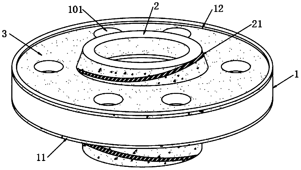
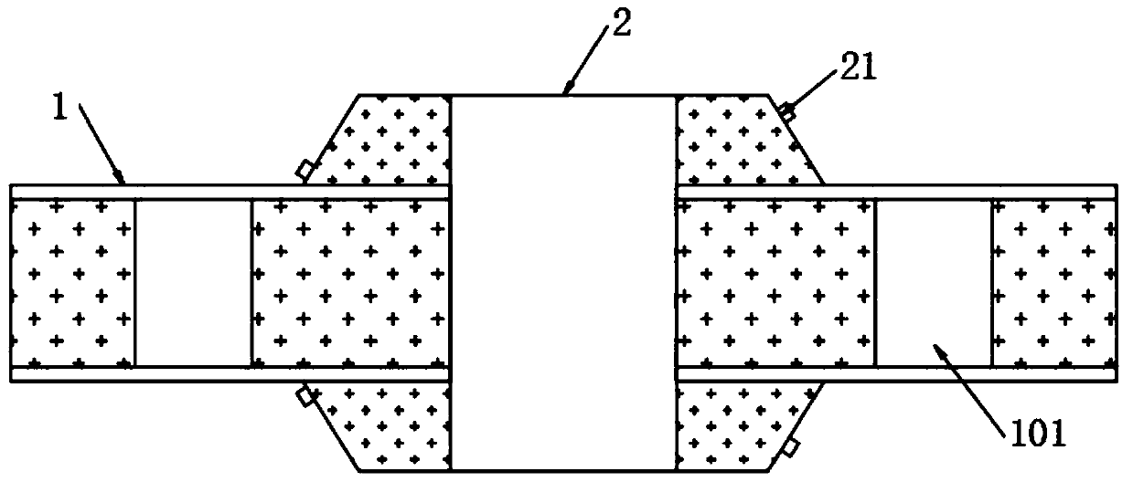
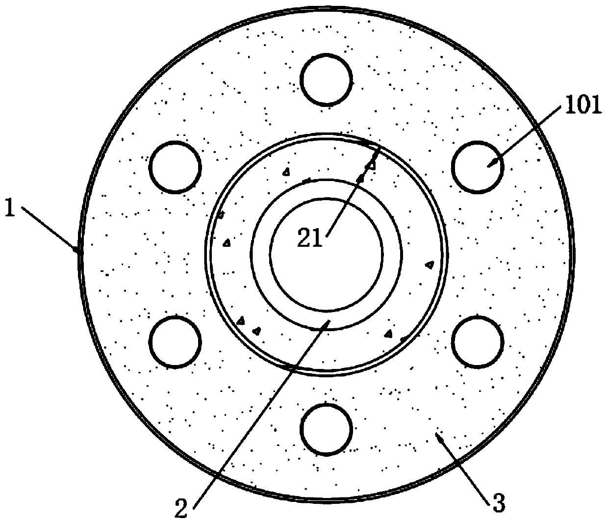
[0032] see Figure 1-3 , the present invention provides the following technical solutions: the pressure vessel flange includes a flange plate 1, and the flange plate 1 has several screw holes 101 distributed centrally and symmetrically, the middle position of the top end of the flange plate 1 and the middle position of the bottom end There are symmetrically distributed connecting shaft columns 2 fixed at each place, the outer wall of the connecting shaft column 2 is fixed with threaded protrusions 21 distributed in a spiral shape, and the upper and lower ends of the flange 1 are fixed with protruding flanges 1 There is a limiting groove 12, and there is a groove between the limiting groove 12 and the flange 1.

[0033] In this embodiment: the outer wall of the connecting shaft column 2 is fixed with threaded protrusions 21 distributed in a spiral shape, and the upper and lower ends of the flange 1 are fixed with limiting grooves 12 protruding from the flange 1 to limit There ...

Embodiment 2

[0050] see Figure 1-3 , the present invention provides the following technical solutions: the pressure vessel flange includes a flange plate 1, and the flange plate 1 has several screw holes 101 distributed centrally and symmetrically, the middle position of the top end of the flange plate 1 and the middle position of the bottom end There are symmetrically distributed connecting shaft columns 2 fixed at each place, the outer wall of the connecting shaft column 2 is fixed with threaded protrusions 21 distributed in a spiral shape, and the upper and lower ends of the flange 1 are fixed with protruding flanges 1 There is a limiting groove 12, and there is a groove between the limiting groove 12 and the flange 1.

[0051] In this embodiment: the outer wall of the connecting shaft column 2 is fixed with threaded protrusions 21 distributed in a spiral shape, and the upper and lower ends of the flange 1 are fixed with limiting grooves 12 protruding from the flange 1 to limit There ...


PUM


Abstract

The invention belongs to the technical field of flanges, and particularly relates to a flange for a pressure vessel and a machining method thereof. The flange for the pressure vessel comprises a flange plate. A plurality of screw holes are formed in the flange plate in a central symmetry mode, and connecting shaft columns are symmetrically and fixedly arranged in the middle of the top end of the flange and the middle of the bottom end of the flange plate correspondingly. Spirally distributed threaded protrusions are fixedly arranged on the outer walls of the connecting shaft columns. The limiting grooves are integrally formed in the top end and the bottom end of the flange plate. Through the combination of the threaded protrusions and the limiting grooves, the surface, making contact withthe flange plate, of a gasket can be clamped into one limiting groove when the sealing gasket is installed, a threaded groove matched with the corresponding threaded protrusion is formed in the innerwall of the gasket, and the connecting stability between the gasket and the corresponding connecting shaft column is enhanced. The gasket and the flange plate are in tight contact and are not prone toloosening and slipping, proper pre-tightening force is formed between the flange plate and the gasket, it can be guaranteed that certain sealing specific pressure can be kept when the gasket works, and the use stability of the gasket is enhanced.

Description

technical field [0001] The invention belongs to the technical field of flanges, and in particular relates to a pressure vessel flange and a processing method thereof. Background technique [0002] Pressure vessels are the most widely used equipment in the petrochemical industry and one of the main production tools in the petrochemical industry. Due to process requirements and the need for installation and maintenance of equipment internals, pressure vessels often need to be equipped with vessel flanges. Pressure vessel flanges are divided into integral flanges, loop flanges and arbitrary flanges according to the connection of flange rings. There are three types of standard pressure vessel flanges: Type A flat welding flange, Type B flat welding flange and long neck butt welding flange, among which Type A and Type B flat welding flanges are all arbitrary flanges. Flanges and their gaskets and fasteners are collectively referred to as flange joints. Flange joints are widely u...

Claims


Application Information

Patent Timeline
Patent Type & Authority Applications(China)
IPC IPC(8): B23P15/00B23Q3/06
CPCB23P15/00B23Q3/06
Inventor 富中
Owner 海盐县法兰厂
Why Eureka
Try Eureka