
Drill bit grinding equipment used for motorcycle frame drilling

A motorcycle and grinding technology, which is applied in the direction of drilling/drilling equipment, grinding workpiece support, metal processing equipment, etc., can solve the problems of difficulty, small cutting edge surface, and inability to see clearly

Pending Publication Date: 2020-08-25
常州豪爵铃木摩托车有限公司
View PDF0 Cites 0 Cited by
  • Summary
  • Abstract
  • Description
  • Claims
  • Application Information

AI Technical Summary

Problems solved by technology

[0002] If the cutting edge of the existing twist drill used for drilling motorcycle frames is worn out, for a twist drill with a larger diameter, the naked eye can clearly see the edge surface of the drill bit, and the drill can be directly visually viewed on the edge of the grinder by manually holding the drill bit. Grinding, or using special twist drill edge grinding equipment; for micro twist drills such as Φ1-2mm, the cutting edge surface is small and cannot be seen with the naked eye. Once wear occurs, manual grinding is difficult and can only be discarded.

Method used


Image

  • Drill bit grinding equipment used for motorcycle frame drilling
  • Drill bit grinding equipment used for motorcycle frame drilling
  • Drill bit grinding equipment used for motorcycle frame drilling

Examples


Embodiment Construction

[0030] The present invention will be further described below in conjunction with the accompanying drawings and given embodiments, but is not limited thereto.

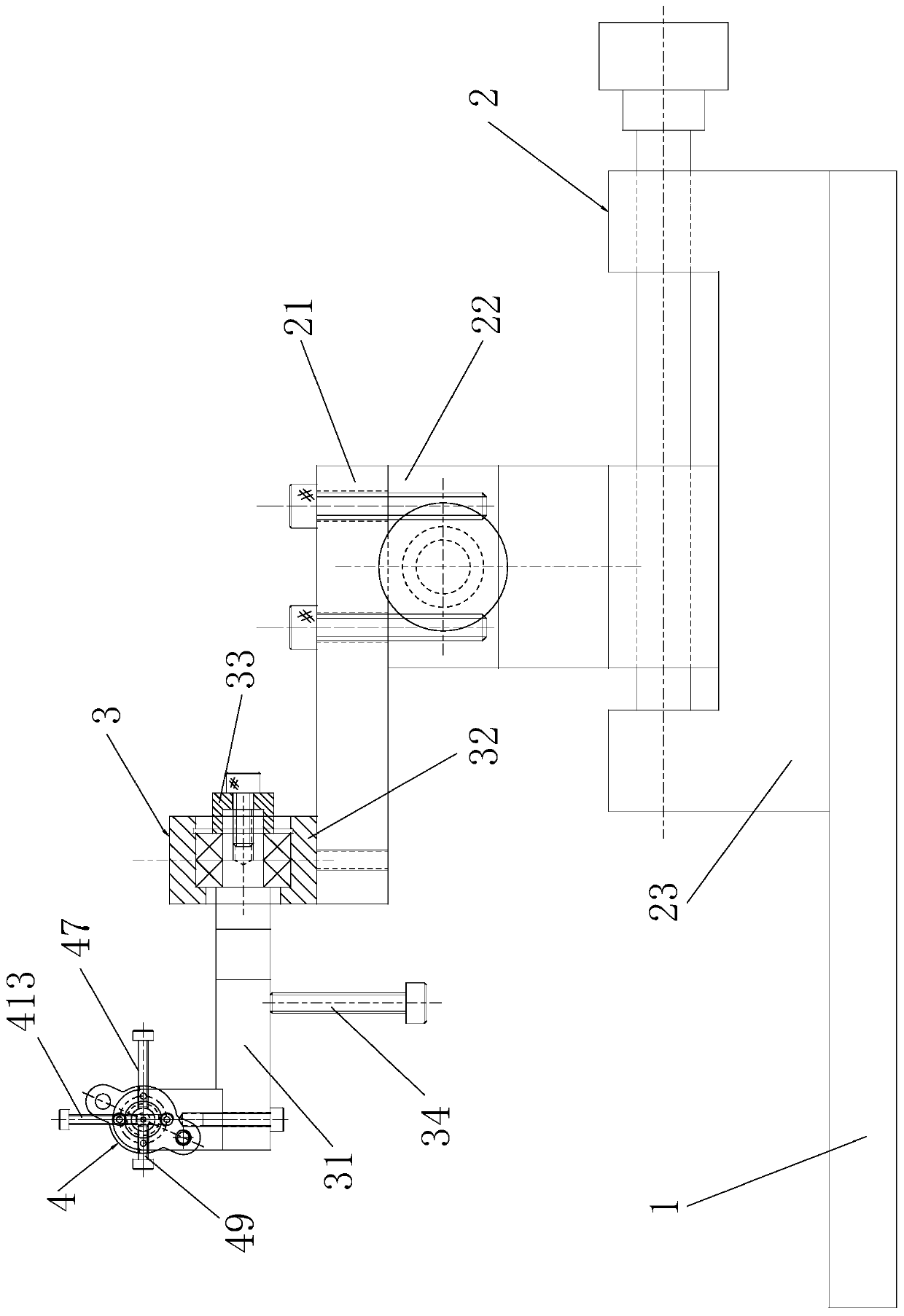
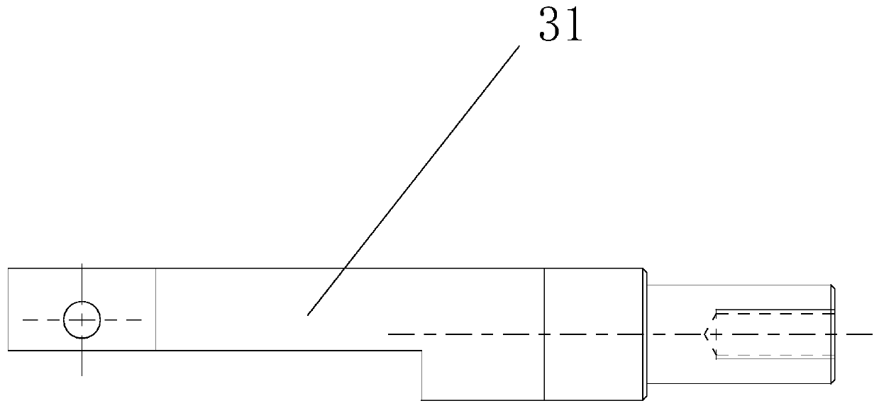
[0031] like Figure 1~12 As shown, a drill grinding equipment for motorcycle frame drilling, including a workbench 1, a reference adjustment and positioning mechanism 2, a grinding clamp assembly rotation mechanism 3 and a workpiece grinding clamp assembly 4,

[0032] The reference adjustment and positioning mechanism 2 is arranged on the workbench 1, the grinding and clamping assembly rotation mechanism 3 is arranged on the reference adjustment and positioning mechanism 2, the grinding assembly 4 is detachably connected with the grinding and clamping assembly rotation mechanism 3,

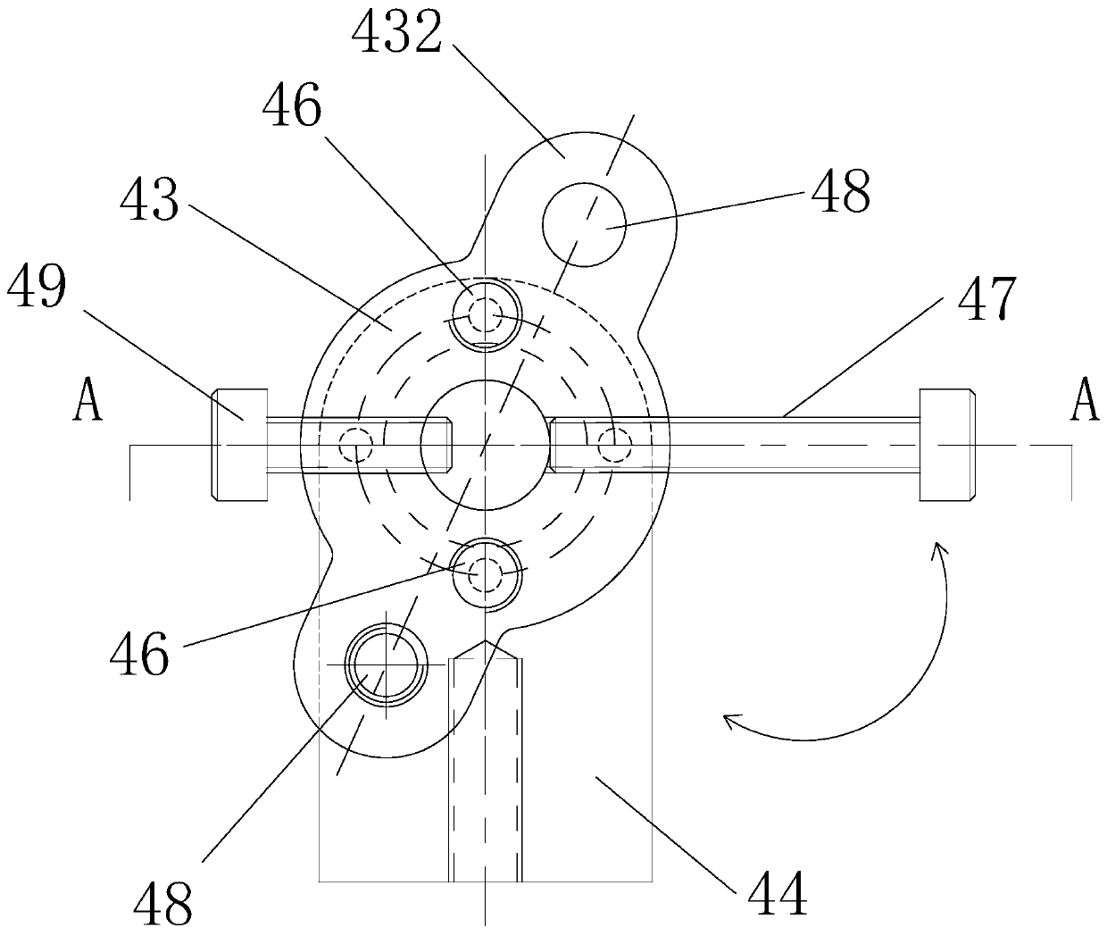
[0033] The workpiece grinding and clamping assembly 4 includes a mandrel 41, a mandrel sleeve 42, a rotating sleeve 43, a shaft seat 44, a ball head positioning rod 45, a glass bead screw 46, a handle 47 and a locking bolt 48. The seat 44 ...


PUM


Abstract

The invention relates to drill bit grinding equipment used for motorcycle frame drilling. The drill bit grinding equipment comprises a workbench, a datum regulating and positioning mechanism, a grinding and clamping component rotation mechanism and a workpiece grinding and clamping component, wherein the datum regulating and positioning mechanism is arranged on the workbench; the grinding and clamping component rotation mechanism is arranged on the datum regulating and positioning mechanism; the grinding component and the grinding and clamping component rotation mechanism are detachably connected; the workpiece grinding and clamping component comprises a core shaft, a core shaft sleeve, a rotary shaft sleeve, a shaft seat, a ball head positioning rod, glass bead screws, a handle and locking bolts, wherein the shaft seat and the grinding and clamping component rotation mechanism are detachably connected; the ball head positioning rod which is radially distributed is arranged near the end part on the core shaft; the core shaft is arranged in the core shaft sleeve; one bolt is screwed into a threaded hole of the rotary shaft sleeve and the threaded hole of the core shaft sleeve in sequence; the locking bolts are arranged in the rotary shaft sleeve and can be screwed into the locking hole of the shaft seat; and the rotary shaft sleeve is also provided with the handle. According tothe drill bit grinding equipment disclosed by the invention, a miniature twist drill bit can be grinded and modified.

Description

technical field [0001] The invention relates to a grinding device, in particular to a drill bit grinding equipment for drilling motorcycle frames. Background technique [0002] If the cutting edge of the existing twist drill used for drilling motorcycle frames is worn out, for a twist drill with a larger diameter, the naked eye can clearly see the edge surface of the drill bit, and the drill can be directly visually viewed on the edge of the grinder by manually holding the drill bit. Grinding, or using special twist drill edge grinding equipment; for micro twist drills such as Φ1-2mm, the cutting edge surface is small and cannot be seen with the naked eye. Once wear occurs, manual grinding is difficult and can only be discarded. . Contents of the invention [0003] The object of the present invention is to provide a kind of drill bit grinding equipment for motorcycle frame drilling which can grind and repair the miniature twist drill bit. [0004] In order to achieve the...

Claims


Application Information

Patent Timeline
Patent Type & Authority Applications(China)
IPC IPC(8): B24B3/26B24B3/24B24B3/00B24B41/06
CPCB24B3/00B24B3/247B24B3/26B24B41/06
Inventor 王建辉
Owner 常州豪爵铃木摩托车有限公司
Learn More