High-rigidity wear-resistant nylon wheel forming device

A technology of forming device and nylon wheel, applied in the field of nylon wheel, can solve the problems of waste of manpower, low degree of automation, deviation of nylon wheel design size, etc., and achieve the effect of convenient and rapid operation and improvement of processing efficiency

Active Publication Date: 2020-08-25
金寨宏伟新材料有限公司
View PDF4 Cites 2 Cited by
  • Summary
  • Abstract
  • Description
  • Claims
  • Application Information

AI Technical Summary

Problems solved by technology

The traditional centrifuge adopts one-stage transmission and relies on V-belt transmission. When it rotates, it is easy to loosen between the upper mold and the lower mold, and it is easy to cause deviation between the formed nylon wheel and the designed size, and the upper mold and the lower mold are use

Method used


Image

  • High-rigidity wear-resistant nylon wheel forming device
  • High-rigidity wear-resistant nylon wheel forming device
  • High-rigidity wear-resistant nylon wheel forming device

Examples


Embodiment Construction

[0030] The following will clearly and completely describe the technical solutions in the embodiments of the present invention with reference to the accompanying drawings in the embodiments of the present invention. Obviously, the described embodiments are only some, not all, embodiments of the present invention. Based on the embodiments of the present invention, all other embodiments obtained by persons of ordinary skill in the art without making creative efforts belong to the protection scope of the present invention.

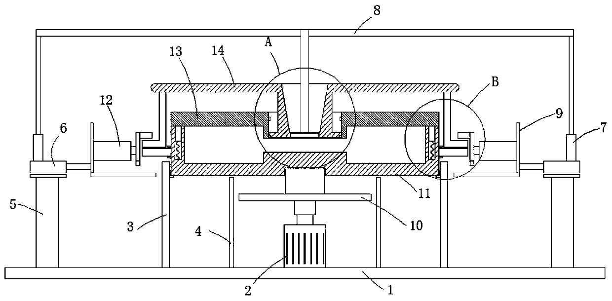
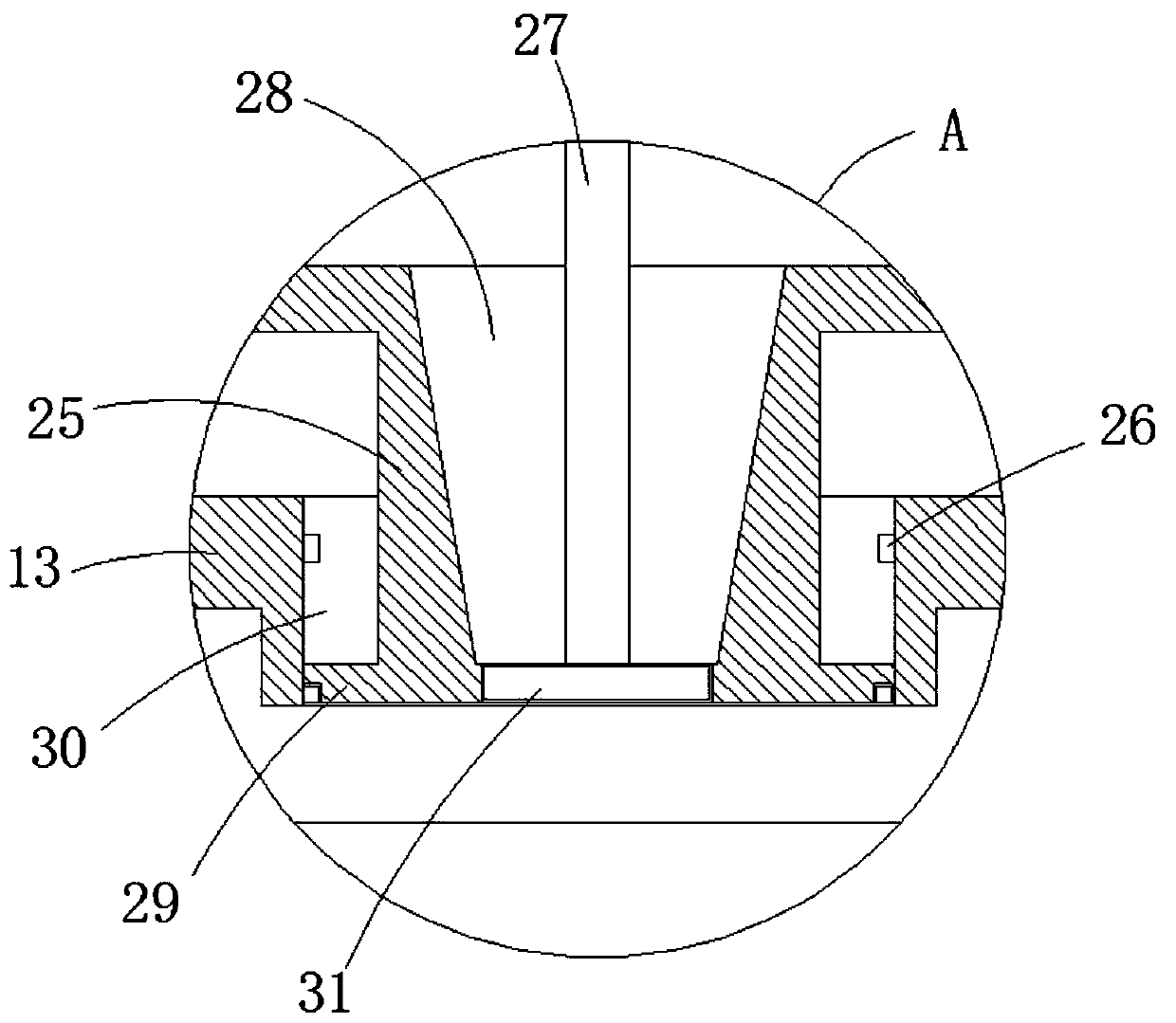
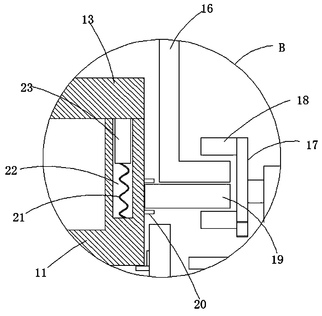
[0031] see Figure 1-4 , a high-rigidity wear-resistant nylon wheel forming device, including a lower mold 11, an upper mold 13, a rotary drive mechanism supported on the bottom of the lower mold 11, and a pressing mechanism located above the upper mold 13.

[0032] The rotary drive mechanism includes a first motor 2 and a turntable 10 coupled with the output shaft of the first motor 2 .

[0033] The bottom of the lower mold 11 is coaxially fixed to the turnt...


PUM


Abstract

The invention discloses a high-rigidity wear-resistant nylon wheel forming device which comprises a lower die, an upper die, a rotation drive mechanism supported on the bottom part of the lower die, and a pressing mechanism arranged above the upper die. The rotation drive mechanism comprises a first motor and a rotary plate connected with an output shaft of the first motor; the bottom part of thelower die is coaxially and fixedly connected to the rotary plate; a lower clamping plate is rotatably arranged on the outer wall of the lower die in a sleeving way; the upper die is movably arranged above the lower die; the upper die and the lower die are connected through a guiding mechanism; a cavity for forming a nylon wheel is formed between the upper die and the lower die; a through hole coaxial to the rotary plate is formed in a shell of the upper die; two annular limiting lugs are distributed in the through hole along the axial direction; and the pressing mechanism comprises a pressingplate, a material injection pipe fixed onto the pressing plate, and an upper clamping plate fixed to the bottom part of the pressing plate. The high-rigidity wear-resistant nylon wheel forming deviceprovided by the invention is simple in structure, convenient to use during die opening and closing, capable of being rotated as a whole after the upper die and the lower die are formed, used for forming the nylon wheel by utilizing a centrifugal force, ingenious in structure design, and high in working efficiency.

Description

technical field [0001] The invention relates to the field of nylon wheels, in particular to a high-rigidity wear-resistant nylon wheel forming device. Background technique [0002] At present, due to its non-toxic, light weight, wear-resistant and other excellent properties, nylon is widely used to replace metals such as copper in machinery, chemical industry, instrumentation, automobiles and other industrial fields. MC nylon with more outstanding performance can even directly replace metal products such as copper, stainless steel, and aluminum alloy. Reduce user costs and prolong service life. [0003] The structural cavity of the existing molding die is hollow, and the specified inner hole size of the nylon wheel product is centrifugally formed by the specified weight of the raw material liquid under the action of a relatively high centrifugal force. At present, the rotation speed of the centrifuge is about 1000r / min to provide the required centrifugal force. However, u...

Claims


Application Information

Patent Timeline
IPC IPC(8): B29C41/04B29C41/36B29C41/38B29K77/00B29L31/32
CPCB29C41/045B29C41/36B29C41/38B29K2077/00B29L2031/322
Inventor 罗会鹏曹富沐王亮李国红叶立奎
Owner 金寨宏伟新材料有限公司
Why Eureka
Try Eureka