Method for erecting scaffold platform between rudder horns and method for measuring deviation of upper and lower rudder holes of rudder horns

A measurement method and scaffolding technology, applied in the direction of berth, ship design, ship parts, etc., can solve the problems that affect the efficiency of the hoisting progress of the berth and occupy the large door crane of the berth, so as to reduce the use time, reduce labor, and improve the progress efficiency. Effect

Active Publication Date: 2020-08-25
中船澄西扬州船舶有限公司
View PDF6 Cites 3 Cited by
  • Summary
  • Abstract
  • Description
  • Claims
  • Application Information

AI Technical Summary

Problems solved by technology

[0002] As an important item on the berth, the rudder system section is related to the ship's power system. The positioning accuracy of the rudder system is very high. Because the rudder system section is installed and positioned, the temperature deviation of the left and right sides does not exceed 3 degrees. Generally, the rudder system section is hoisted at night. , and the height is about ten meters from the ground. Usually, the scaffolding needs to be fully matched after the stage hoisting. It is used to locate the deviation value of the rudder hole and take up a long time for the large portal crane of the berth, which affects the efficiency of the hoisting progress of the berth.

Method used


Image

  • Method for erecting scaffold platform between rudder horns and method for measuring deviation of upper and lower rudder holes of rudder horns
  • Method for erecting scaffold platform between rudder horns and method for measuring deviation of upper and lower rudder holes of rudder horns
  • Method for erecting scaffold platform between rudder horns and method for measuring deviation of upper and lower rudder holes of rudder horns

Examples


Embodiment Construction

[0048] The present invention will be further described below in conjunction with the accompanying drawings and embodiments, which are only used to explain the present invention and do not limit the protection scope of the present invention.

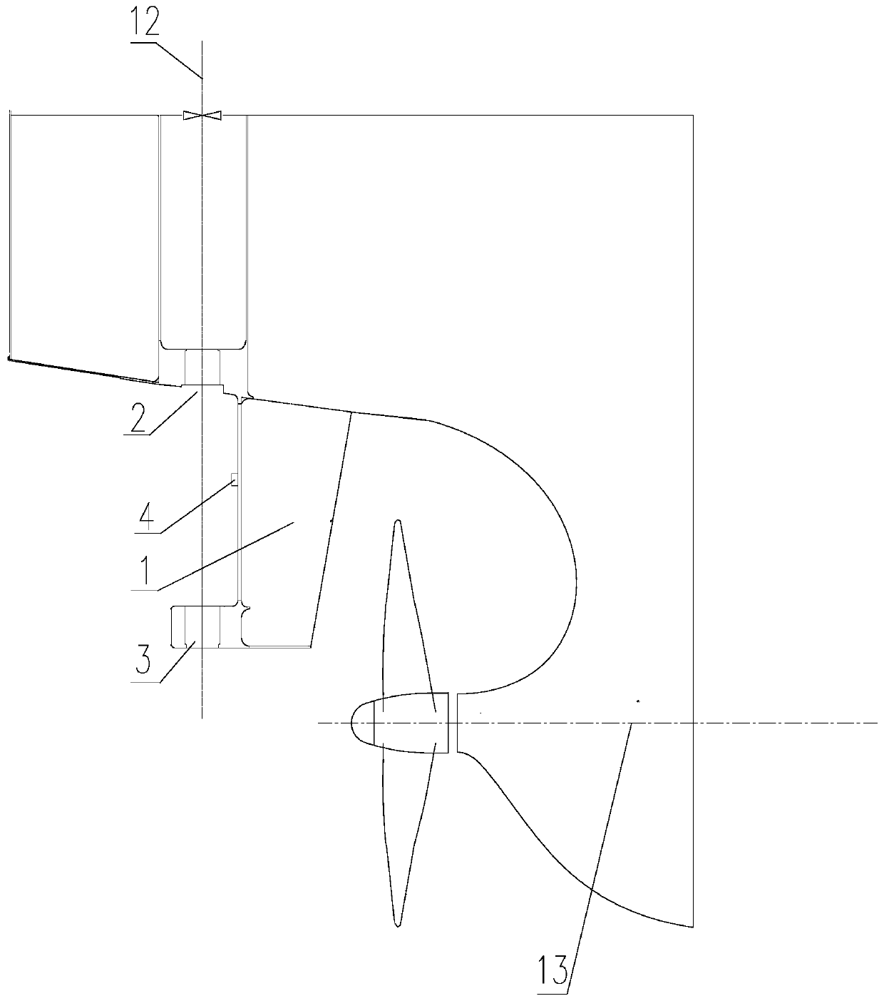
[0049] like Figure 1-13 As shown, a method for erecting a scaffolding platform between hanging rudder arms comprises the following steps:

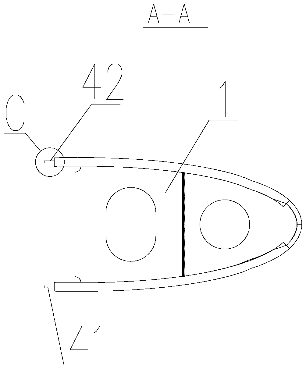
[0050] (1) In the segmental reverse construction stage of the rudder system, the rudder system is placed on the segmented pier 5 on the ground, and the scaffold eye plate 4 is welded on the hanging rudder arm 1, and the scaffold eye plate is located on the inverted rudder arm Between the lower rudder hole 3 and the upper rudder hole 2, the scaffold eye plate 4 is set inclined to the direction of the upper rudder hole of the rudder arm;

[0051] (2) The rudder system enters the painting room in sections for paint spraying;

[0052] (3) After the rudder system section leaves the painting room, the ru...


PUM


Abstract

The invention belongs to the technical field of ship and discloses a method for erecting a scaffold platform between rudder horns. The method comprises the following steps of (1) welding scaffold eyeplates on the rudder horns in a rudder system section inverse construction stage; (2) enabling a rudder system section to enter a coating room for paint spraying; (3) after the rudder system section is out of the coating room, making the rudder system section be in an inverted state, and be between a lower rudder hole and an upper rudder hole of the inverted rudder horn, utilizing the scaffold eyeplates, a bracket, a vertical pipe and a transverse pipe, pre-building the inverted scaffold platform; and (4) hoisting the rudder system section on an obliquely-arranged shipway, locating a stern ison the downstream of the shipway, at the moment, making the rudder system section be in a normal state and the scaffold platform between rudder horns be in a normal state, obliquely arranging the scaffold eye plates upwards, horizontally arranging the bracket, and completing erection of the scaffold platform between the rudder horns. The invention further discloses a method for measuring deviation of upper and lower rudder holes of the rudder horns. Scaffold erecting time is saved, and cost is reduced.

Description

technical field [0001] The invention belongs to the technical field of ships, and in particular relates to a method for erecting a scaffolding platform between rudder arms and a method for measuring the deviation of upper and lower rudder holes of the rudder arms. Background technique [0002] The rudder system segment is an important item for the ship’s berth, which is related to the ship’s power system. The positioning accuracy of the rudder system is very high. Because the temperature deviation of the rudder system segment is not more than 3 degrees to the starboard and starboard sides, the rudder system segment is usually hoisted at night. , and the height is about ten meters above the ground. In the early stage, the auxiliary scaffolding is usually needed after the segmental hoisting to measure the deviation value of the positioning rudder hole. It takes a long time for the large gantry crane of the berth, which affects the efficiency of the hoisting progress of the bert...

Claims


Application Information

Patent Timeline
Patent Type & Authority Applications(China)
IPC IPC(8): B63C5/02B63B73/00B63B73/20B63B71/00
CPCB63C5/02B63B73/00B63B73/20B63B71/00B63C2005/025
Inventor 刘旺周丹殷义猛章印平
Owner 中船澄西扬州船舶有限公司
Why Eureka
Try Eureka