Pavement cement paving device for road and bridge construction

A bridge construction and cement technology, which is applied in the field of pavement cement tiling devices for road and bridge construction, can solve the problems of inability to adjust, bulky and the like

Active Publication Date: 2020-08-25
CHINA RAILWAY 21ST BUREAU GROUP THE FOURTH ENG
View PDF7 Cites 5 Cited by
  • Summary
  • Abstract
  • Description
  • Claims
  • Application Information

AI Technical Summary

Problems solved by technology

[0003] The device used for paving cement pavement in the prior art is relatively heavy and cannot be adjusted according to the width of the pavement; in the process of laying the pavement, it is necessary to evenly distribute the cement concrete accumulated in the middle of the pavement, so that the two sides of the pavement and the middle of the pavement The height of the cement concrete is consistent, and the cement concrete needs to be leveled to reduce the hollowing phenomenon in the cement concrete; the road surface needs to be smoothed according to the height of the road surface

Method used


Image

  • Pavement cement paving device for road and bridge construction
  • Pavement cement paving device for road and bridge construction
  • Pavement cement paving device for road and bridge construction

Examples


Embodiment 1

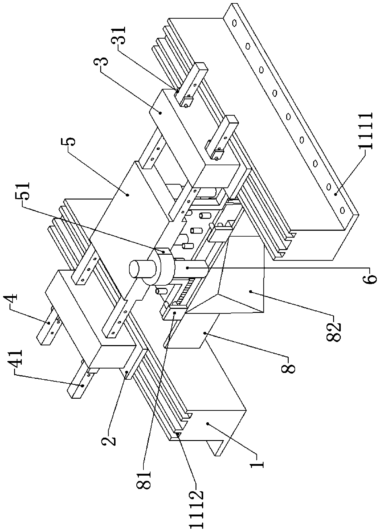
[0028] Present embodiment 1 has introduced a kind of road cement paving device for road and bridge construction, as figure 1 As shown, including the ground beam bases 1 laid symmetrically on both sides of the road surface, the bottoms of the two ends of the ground beam bases 1 that are far away from each other are provided with widened bottoms 1111, and fixed holes are evenly opened on the widened bottoms 1111, so Two rails 1112 are longitudinally arranged on the top of the ground beam seat 1, and a bottom plate 2 is provided on the top of the ground beam seat 1, and the four corners of the bottom of the bottom plate 2 are provided with electric wheels 2111 corresponding to the positions of the rails 1112 and matched in size. , the inside of the chassis 3 is provided with a storage battery for powering the electric wheel 2111. When in use, the electric wheel 2111 at the bottom of the bottom plate 2 enters the inside of the track 1112, and the battery inside the chassis 3 is pow...

Embodiment 2

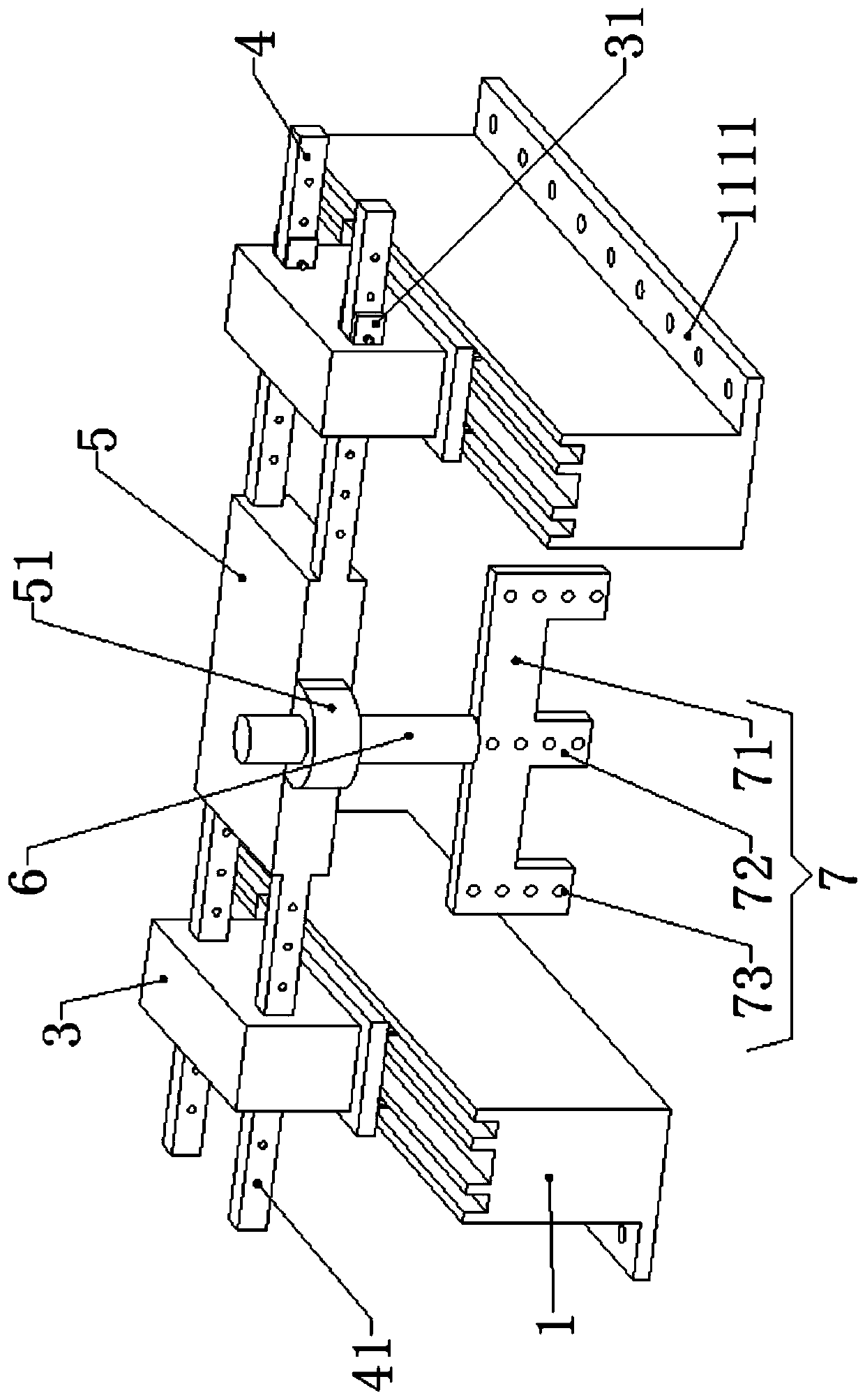
[0031] This embodiment 2 has introduced a kind of pavement cement tiling device for road and bridge construction, 1. comprises ground beam seat 1 that is symmetrically laid on both sides of the road surface, and the top of described ground beam seat 1 is all provided with base plate 2, and the top of described base plate 2 Both are welded with a chassis 3, and two beams 4 are movably installed between the two chassis 3, and a main plate 5 is fixed in the middle of the two beams 4, and a head block 51 is provided extending outward from the middle of the front end of the main plate 5 , the middle of the head block 51 is connected with a main rod 6, and the bottom of the main rod 6 extends to the bottom of the main plate 5 and is welded with an E-shaped frame 7, and the E-shaped frame 7 includes an upper fixing plate 71 at the top. The bottom of the upper fixing plate 71 is equidistantly provided with three vertical fixing plates 72, the vertical fixing plates 72 are equipped with...

Embodiment 3

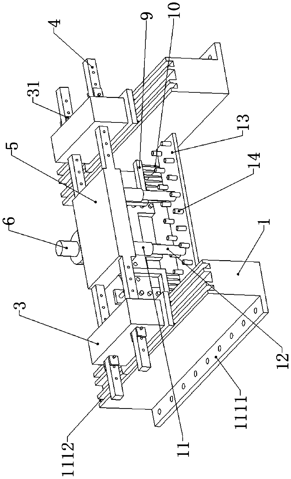
[0034] This embodiment 3 introduces a pavement cement paving device for road and bridge construction, including ground beam bases 1 symmetrically laid on both sides of the road surface, the tops of the ground beam bases 1 are all provided with base plates 2, and the tops of the base plates 2 are all welded There is a cabinet 3, two beams 4 are movably installed between the two cabinets 3, a main plate 5 is fixed in the middle of the two beams 4, a cavity is arranged in the middle of the main plate 5, and the top of the cavity is A motor 16 is installed, and the top of the L-shaped square tube 9 extends to the inside of the cavity to be provided with a round stem 91, and the outer wall of the top of the round stem 91 is fixed with a driven gear 15, and the output end of the motor 16 Extending to the bottom of the cavity, a driving gear 17 is installed, and the driving gear 17 and the two driven gears 15 are all meshed with each other. A head block 51 is provided in the middle of...


PUM


Abstract

The invention relates to the technical field of road and bridge construction and especially relates to a pavement cement paving device for road and bridge construction. The device comprises ground beam seats which are symmetrically paved on two sides of a road surface. Bottom plates are arranged at the tops of the ground beam seats. Cases are welded to the tops of the bottom plates. The bottom ofa main rod extends below a main plate block and is welded with an E-shaped frame; a vertical plate is mounted at a front end of the E-shaped frame; a flow guide block for pushing cement concrete towards two sides of the road surface is fixed in the middle of the front end of the vertical plate; two L-shaped square pipes are arranged in the middle of the bottom of the main plate block; rake teeth for raking cement concrete are uniformly arranged at the bottom of the L-shaped square tube; and inner rods are elastically installed at the bottom of an outer pipe, a paving plate is jointly installedat the bottoms of the two inner rods, and pressure applying cylinders are evenly arranged at the top of the paving plate. The device is ingenious in structure, the cement concrete stacked in the middle of a road surface is pushed to the two sides of the road surface through the arrangement of the flow guide block, and the road surface is flattened through the arrangement of the rotating L-shapedsquare pipes; and the road surface is flattened through the paving plate so that a pavement paving effect is good.

Description

technical field [0001] The invention relates to the technical field of road and bridge construction, in particular to a pavement cement paving device for road and bridge construction. Background technique [0002] Existing highway pavement is generally cement pavement or asphalt pavement, and cement concrete pavement refers to a pavement with cement concrete as the main material for the surface layer, referred to as concrete pavement. Also known as rigid pavement, commonly known as white pavement, it is a high-grade pavement. With the development of my country's transportation industry and the continuous improvement of road performance, the requirements for road surface roughness are getting higher and higher for road construction. Road surface roughness is the most important indicator of road performance. [0003] The device used for paving cement pavement in the prior art is relatively heavy and cannot be adjusted according to the width of the pavement; in the process of ...

Claims


Application Information

Patent Timeline
Patent Type & Authority Applications(China)
IPC IPC(8): E01C19/18
CPCE01C19/187
Inventor 胡冬花姜涛孙战伟彭艳孙银花牛明星王培振
Owner CHINA RAILWAY 21ST BUREAU GROUP THE FOURTH ENG
Why Eureka
Try Eureka