Strand-like material laying device for cutting the ground and inserting strand-like material into the ground
What is AI technical title?
AI technical title is built by PatSnap AI team. It summarizes the technical point description of the patent document.
a technology of laying device and strand-like material, which is applied in the direction of cable laying vessel, excavation, pipe laying vessel, etc., can solve the problems of inability to apply in the case of relatively low flexibility and “endless” length of strand-like material, and achieve the effect of smooth feeding
Active Publication Date: 2010-11-30
FOCKERSPERGER JR WALTER
View PDF55 Cites 6 Cited by
Summary
Abstract
Description
Claims
Application Information
AI Technical Summary
This helps you quickly interpret patents by identifying the three key elements:
Problems solved by technology
Method used
Benefits of technology
Benefits of technology
"The present invention provides a strand-like material laying device for an appliance for laying any kind of strand-like material into the ground. The device is designed to smoothly feed the material into a trench while compensating for changing lateral forces acting on the cutting and inserting elements. It includes a first unit for cutting the material and guiding it into the trench, with a plurality of first elements connected in series like a flexible chain, each with a cutting edge. The cutting edges are offset in depth direction of the device to increase the bending radius of the material, preventing it from bending below a minimum allowable bending radius. The device can be moved in a longitudinal direction and is designed to lay the material at a bottom of the trench. It can be adjusted to different ground conditions and has a pivotal movement limited to a predetermined maximum angle. The device can be equipped with different cutting tips for adaptation to different ground conditions."
Problems solved by technology
However, such appliances are not appropriate in cases where strand-like material of relatively low flexibility and of “endless” length, such as more rigid steel pipes like gas pipes, oil pipes, etc., are to be laid.
Method used
Image
Click on the blue label to locate the original text in one second.
Reading with bidirectional positioning of images and text.
Examples
Embodiment Construction
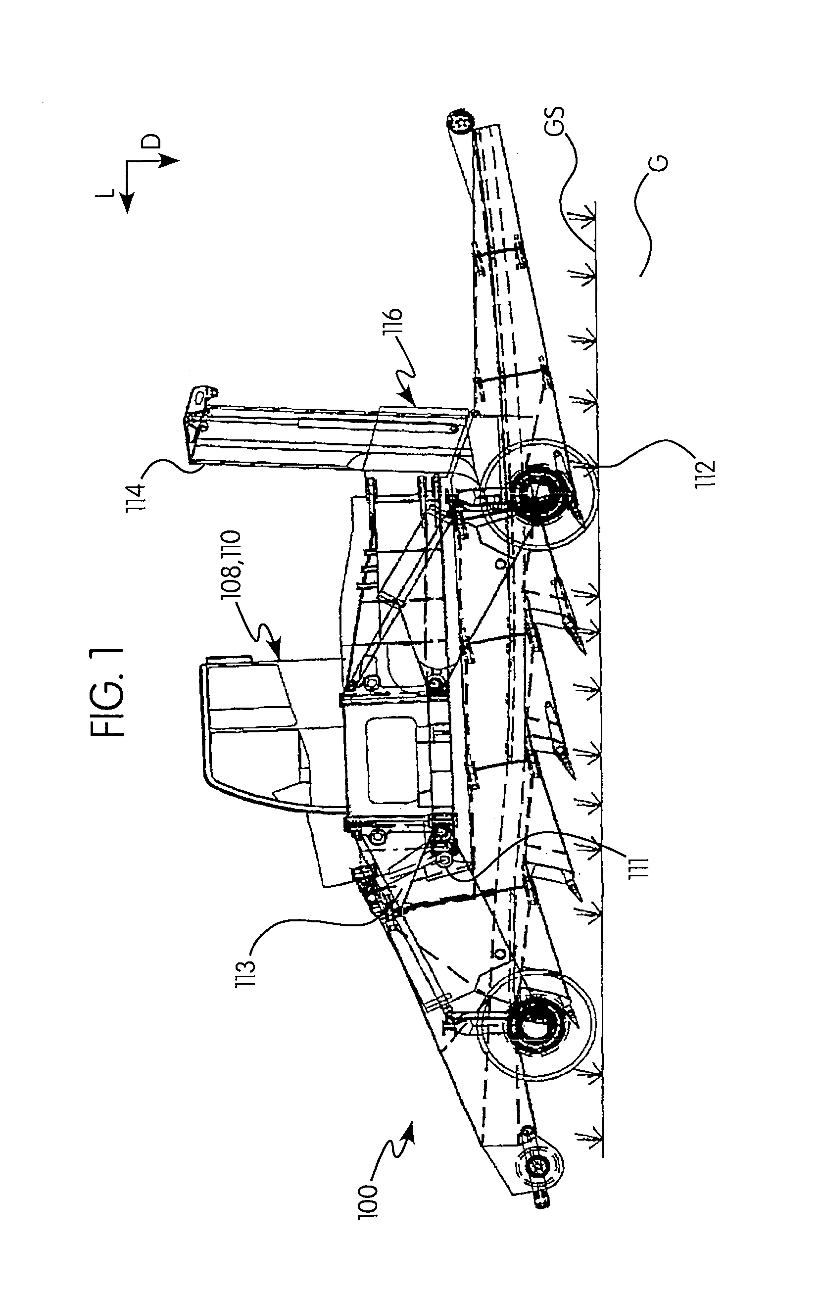
[0037]Reference will now be made with FIGS. 1 to 10 to the structure and effects of preferred embodiments of the invention.
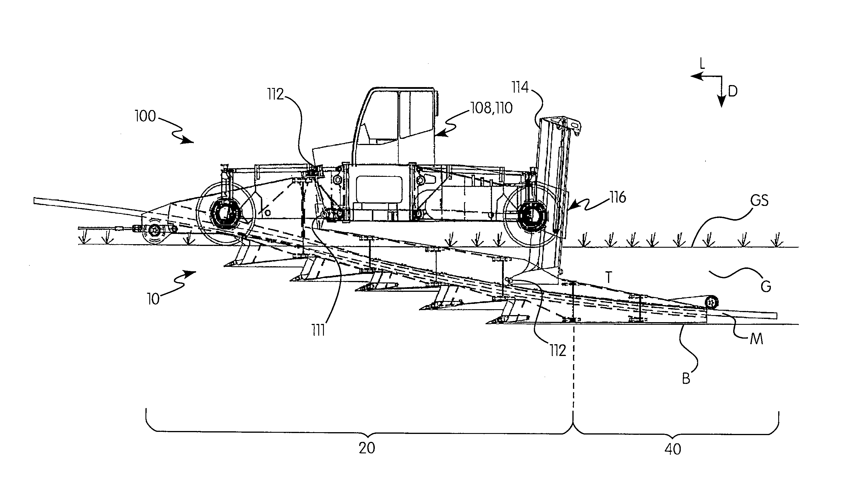
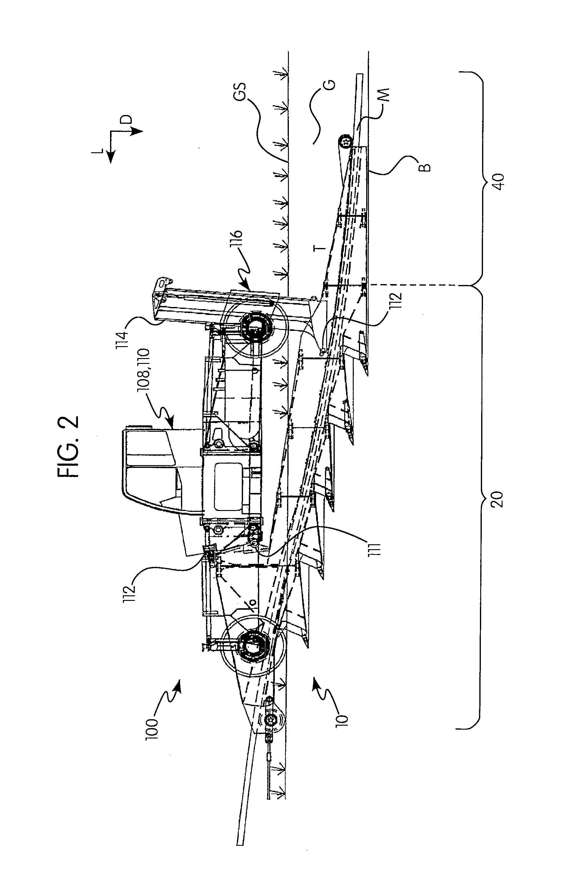
[0038]Referring to FIGS. 1 to 10, the ground surface is denoted by GS, the ground is denoted by G, a trench formed by a strand-like material laying device according to the present invention is denoted by T, and a strand-like material laid in the trench T is denoted by M. Arrows L, D, and W denote a longitudinal direction (or direction of movement), a depth direction, and a width direction (or lateral direction), respectively, of the strand-like material laying device 10.
[0039]FIGS. 1 to 10 show a strand-like material laying device 10 according to an embodiment of the present invention, which is carried by an off-road steerable, four-wheeled chassis frame 100 as seen from FIGS. 1 to 3. As it is illustrated in FIG. 2, the strand-like material laying device 10 carried by the chassis frame 100 is configured to substantially vertically immerse into the ground G when ...
PUM
Abstract
A strand-like material laying device for an appliance for laying any kind of strand-like material into the ground is disclosed. The strand-like material laying device is designed to lay a more rigid strand-like material such as steel pipes into the ground, and assures that the strand-like material to be laid can smoothly be fed into a trench formed in the ground without risking that a bending radius thereof falls below a minimum allowable bending radius which depends on the type of the strand-like material to be laid. The strand-like material laying device can also be immersed into the ground to form a subterranean trench while being moved in a longitudinal direction.
Description
FIELD OF THE INVENTION[0001]The present invention relates generally to a strand-like material laying device for appliances for laying strand-like material of endless length, such as steel pipes, conduits, cables, etc., into a trench formed in the ground.BACKGROUND OF THE INVENTION[0002]Various appliances have been suggested which include a device for forming a trench having substantially vertical side walls in the ground, and for laying strand-like material of endless length, such as conduits, pipes and cables, into the trench. It should be noted that “endless length” designates a material which is very long in comparison with the length of the device laying the material, and does not require that the material be of infinite length. Such appliances are described e.g. in WO 86 / 00536 A1, U.S. Pat. No. 3,747,357, U.S. Pat. No. 3,486,344, U.S. Pat. No. 3,486,344, U.S. Pat. No. 3,429,134, DE 1 189 602 A1, DE 32 45 625 A1, DE 25 29 285 A1, DE 28 06 379 A1 or DE 491 887 B1 and typically co...
Claims
Application Information
Patent Timeline
Application Date:The date an application was filed.
Publication Date:The date a patent or application was officially published.
First Publication Date:The earliest publication date of a patent with the same application number.
Issue Date:Publication date of the patent grant document.
PCT Entry Date:The Entry date of PCT National Phase.
Estimated Expiry Date:The statutory expiry date of a patent right according to the Patent Law, and it is the longest term of protection that the patent right can achieve without the termination of the patent right due to other reasons(Term extension factor has been taken into account ).
Invalid Date:Actual expiry date is based on effective date or publication date of legal transaction data of invalid patent.

