Blowout preventer for oil field workover treatment

A blowout preventer and workover technology, which is applied in wellbore/well components, earthwork drilling, sealing/isolation, etc., can solve the problems of unqualified safety performance, safety accidents, inconvenient operation, etc., and achieve volume reduction and The effect of weight, enhanced safety factor, and convenient installation on site

Inactive Publication Date: 2020-08-25
LINQU LI SHENG PETROLEUM MACHINERY EQUIP
View PDF0 Cites 3 Cited by
  • Summary
  • Abstract
  • Description
  • Claims
  • Application Information

AI Technical Summary

Problems solved by technology

The existing blowout preventer is equipped with two or more layers of sealing rams, each layer has different functions, and each layer can only realize one function, especially the fully sealed ram, which has insufficient efficiency and safety performance. The fully-sealed ram structure is to control whether the seal is tight or not by tightening the tightness of the screw rod when the rams at both ends are parallel to the position of the central through hole. The safety performance is not good enough, and the seal is vulnerable to the impact of the fluid in the well and thus fails. Due to the multi-layer structure The design of the wellhead makes the height of the wellhead too high during the construction process, and it is inconvenient to operate during the construction process of pipes and rods. The wellhead is too high to cause safety accidents. The original blowout preventer is extremely heavy in the process of transportation, loading and unloading, on-site installation, movement, and maintenance. , inconvenient, easily lead to safety accidents

Method used


Image

  • Blowout preventer for oil field workover treatment
  • Blowout preventer for oil field workover treatment
  • Blowout preventer for oil field workover treatment

Examples


Embodiment Construction

[0022] The technical solutions of the present invention will be described in detail below in conjunction with embodiments. The following examples are only used to illustrate the technical solutions of the present invention more clearly, and therefore are only examples, rather than limiting the protection scope of the present invention.

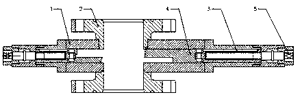
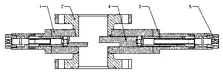
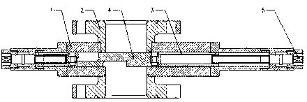
[0023] like Figure 1-3 As shown, a blowout preventer for oilfield workover operations includes a body 1, and a vertical through hole is arranged in the body 1, and the pipe string and tools can pass up and down smoothly in the vertical through hole. The upper and lower sides of the body 1 There is a flange 2 at the end, and a set of two opposite sealing rams 3 are provided for sealing and sliding in the inner cavity of the body 1, which are used to realize the full sealing of the blowout preventer or the half sealing of the blowout preventer through the change and cooperation of the relative position Function;

[0024] A rubber block 4 is e...


PUM


Abstract

The invention belongs to the technical field of oil field workover treatment appliances, and provides a blowout preventer for oil field workover treatment. The blowout preventer comprises a body, flanges are mounted on the upper end and the lower end of the body, a set of two seal gate plates which are oppositely mounted are slidingly mounted in an inner cavity of the body, and are used for achieving a full seal function of the blowout preventer or a semi seal function of the blowout preventer through change fit of opposite positions, rubber blocks are embedded on the seal gate plates, and areused for sealing a string of the blowout preventer or full close, tightening release shafts extending out of the blowout preventer body are connected to the two seal gate plates, and are used for driving the seal gate plates to move oppositely or move in a reverse manner, a seal structure is used, the technical effects of two seal functions of semi seal and full seal can be achieved, the size andthe weight of the whole device can be reduced, the safety coefficient can be increased, transport, maintaining, loading, unloading and site mounting are convenient, the blowout preventer is portableand easy to operate, the structure is simple, use is convenient, and the blowout preventer is suitable for large-scale popularization and use.

Description

technical field [0001] The invention relates to the technical field of equipment for oil field workover operations, in particular to a blowout preventer for oil field workover operations. Background technique [0002] At present, in the process of lifting and lowering pipes and rod strings in oil field workover operations, if a blowout sign occurs, the usual measures are: to close the wellbore and realize the sealing of the wellhead according to the function of selecting the corresponding layer number according to whether there is a pipe string in the wellbore. The existing blowout preventer is equipped with two or more layers of sealing rams, each layer has different functions, and each layer can only realize one function, especially the fully sealed ram, which has insufficient efficiency and safety performance. The fully-sealed ram structure is to control whether the seal is tight or not by tightening the tightness of the screw rod when the rams at both ends are parallel t...

Claims


Application Information

Patent Timeline
Patent Type & Authority Applications(China)
IPC IPC(8): E21B33/06
CPCE21B33/062
Inventor 张波黄和平张利张兴瑞郝建广李鹏徐海波王东波宋江涛李清征张红斌蔡立彭立兴李虎吴文波刘永峰赵斌陈浩赵润峰王志船张娜张阳
Owner LINQU LI SHENG PETROLEUM MACHINERY EQUIP
Why Eureka
Try Eureka