
Automatically walking grouting trolley device for subway shield construction

An automatic walking, subway shield technology, applied in large fields, can solve the problems of slow speed, troublesome operation, low grouting efficiency behind the wall, etc., and achieve the effect of simple structure, strong practicability, and rapid grouting

Active Publication Date: 2020-08-25
BEIJING MUNICIPAL CONSTR +1
View PDF5 Cites 2 Cited by
  • Summary
  • Abstract
  • Description
  • Claims
  • Application Information

AI Technical Summary

Problems solved by technology

[0003] The interior of the existing grouting trolley only serves to store the prepared mud. When the mud is used up, it is necessary to remove the grouting trolley from the tunnel again, and then re-inject the cement slurry. The operation is more troublesome, so that The efficiency of grouting behind the wall is reduced and the speed is slowed down

Method used


Image

  • Automatically walking grouting trolley device for subway shield construction
  • Automatically walking grouting trolley device for subway shield construction
  • Automatically walking grouting trolley device for subway shield construction

Examples


Embodiment 1

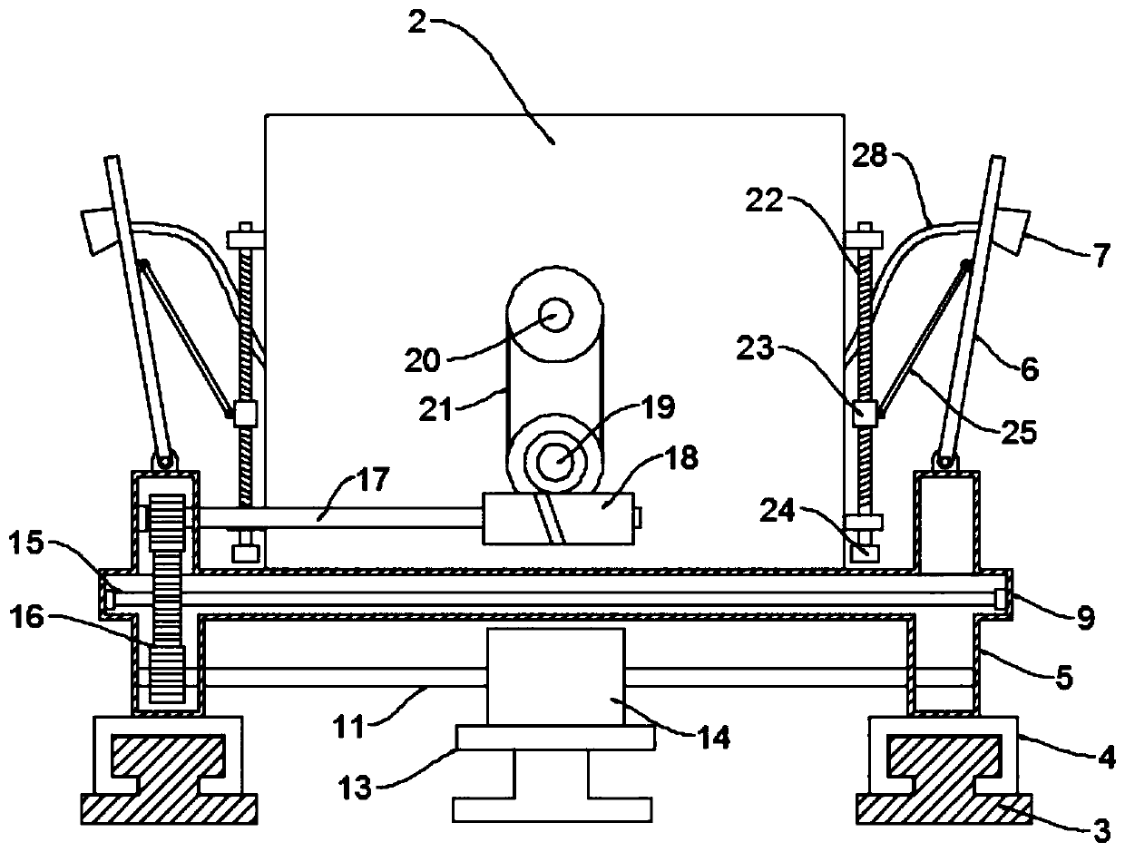
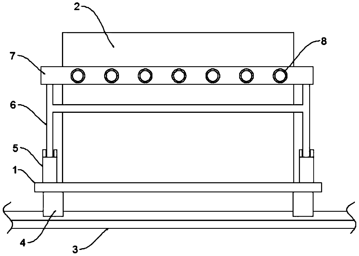
[0022] see Figure 1~3 , in an embodiment of the present invention, a self-propelled grouting trolley equipment for subway shield construction, including a trolley frame 1 and a slurry storage box 2 arranged on the trolley frame 1, the trolley frame 1 is two The ends are all provided with horizontal tubes 9 and the ends of each horizontal tube 9 are provided with side convex body 5, the bottom end of the side convex body 5 is provided with a walking slide 4 and the sliding buckle of the walking slide 4 is fixed on the tunnel ground. On the walking guide rail 3, a rotating horizontal shaft 11 is arranged between the two side convex bodies 5 and a walking driving gear 14 is installed on the rotating horizontal shaft 11. 13, and the outer wall of the slurry storage box 2 is provided with a travel motor 19 and a drive cross shaft 17, and the drive cross shaft 17 is connected to the output end of the travel motor 19 through a worm gear transmission pair 18. A transmission cross sh...

Embodiment 2

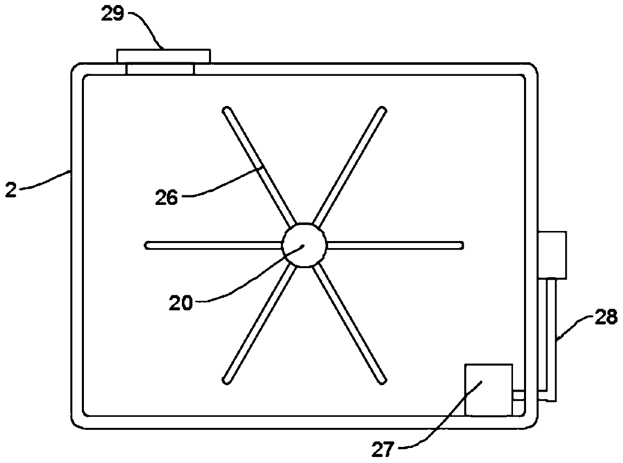
[0027] The difference between the embodiment of the present invention and embodiment 1 is that: the inside of the vehicle platform 1 is also provided with a stirring rod shaft 20 whose end is rotatably connected to the side wall, and a plurality of stirring rods 26 are arranged on the stirring rod shaft 20 One end of the stirring rod shaft 20 is connected to the output end of the travel motor 19 through the transmission unit, and the travel motor 19 can be used to drive the stirring rod shaft 20 to rotate and make the stirring rod 26 on it stir the slurry inside the slurry storage box 2 Avoid solidification or settlement; the transmission unit 21 is a belt drive or a sprocket drive.


PUM


Abstract

The invention discloses an automatically walking grouting trolley device for subway shield construction. The automatically walking grouting trolley device for subway shield construction comprises a trolley rack and a grout storage tank arranged on the trolley rack; two ends of the trolley rack are provided with transverse pipes, the end of each transverse pipe is provided with a side convex body,the bottom end of each side convex body is provided with a walking slide base, the walking slide bases are slidably buckled on walking guide rails fixed on the tunnel ground, a rotating transverse shaft is arranged between the two side convex bodies, a walking driving gear is installed on the rotating transverse shaft, and the walking driving gear is engaged with a walking transverse rack arrangedon the tunnel ground; the outer wall of the grout storage tank is provided with a walking motor and a driving transverse shaft; and two sides of the trolley rack are provided with grouting mechanismsfor spraying out grout in the grout storage tank. The automatically walking grouting trolley device for subway shield construction is simple in structure, the whole trolley can conveniently walk backand forth automatically in a tunnel, rapid grouting can be achieved, operation is convenient and fast, and practicability is high.

Description

technical field [0001] The invention relates to a large field, in particular to a self-propelled grouting trolley equipment for subway shield construction. Background technique [0002] Subway shield tunneling is an important construction technology in urban subway construction, and it is a construction method for digging tunnels underground. It uses the subway shield machine to excavate underground, while preventing the soft ground excavation surface from collapsing or maintaining the stability of the excavation surface, while safely performing tunnel excavation and lining operations inside the machine. The construction process needs to excavate a shaft or a foundation pit at one end of a certain section of the tunnel, hoist the subway shield machine into the installation, and the subway shield machine starts to excavate from the wall opening of the shaft or foundation pit and advances along the designed hole line until To reach the end of another shaft or tunnel in the ho...

Claims


Application Information

Patent Timeline
Patent Type & Authority Applications(China)
IPC IPC(8): E21D11/10
CPCE21D11/105
Inventor 郭飞孔恒张丽丽樊雅丽于春波刘海健张宝亮王凯丽高胜雷田治州
Owner BEIJING MUNICIPAL CONSTR
Learn More