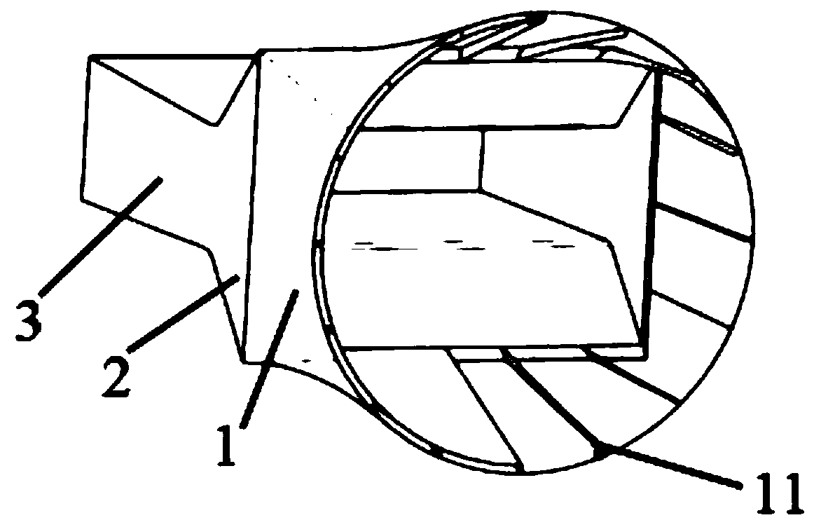
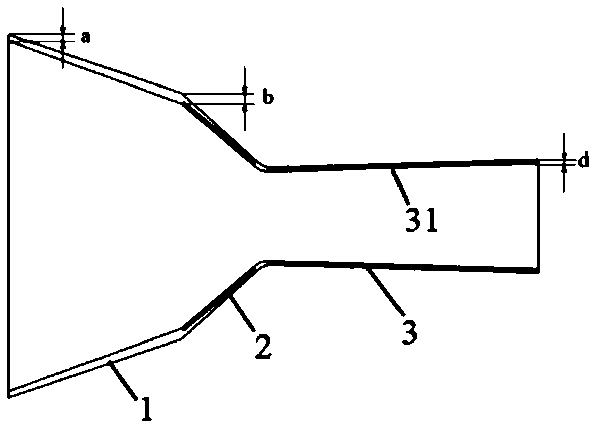
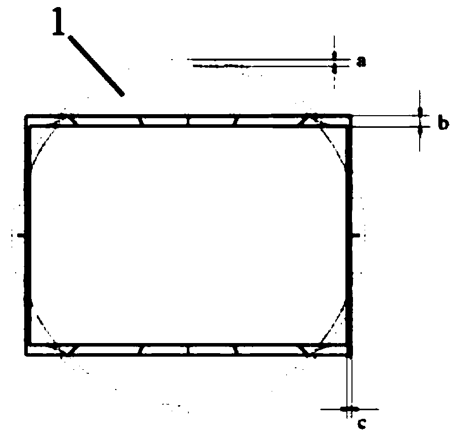
Cooling channel structure suitable for two-dimensional invisible spray pipe

A technology of cooling channels and channels, applied in jet propulsion devices, machines/engines, etc., can solve the problems of uneven cooling effect of components, wall ablation, and high cooling efficiency, so as to avoid excess cooling efficiency and avoid insufficient cooling air volume of the regulating piece. Effect

Active Publication Date: 2020-08-25
AECC SHENYANG ENGINE RES INST
View PDF8 Cites 23 Cited by
  • Summary
  • Abstract
  • Description
  • Claims
  • Application Information

AI Technical Summary

Problems solved by technology

Compared with the nozzle, the axial pressure difference between the main combustion chamber and the afterburner chamber is smaller, and the cooling scheme mostly adopts simple film cooling, but the airflow in the nozzle channel expands and accelerates in the nozzle, and changes from circular to The static pressure of the nozzle from the square section to the expansion section is greatly reduced. If a simple film cooling airflow is used to flow a large amount into the expansion section of the low-pressure area, backflow will occur in the circular to square section and the convergent section, resulting in serious unevenness in the cooling effect of the components. The local cooling efficiency is too high, and local reflow occurs, which will seriously cause wall ablation

Method used


Image

  • Cooling channel structure suitable for two-dimensional invisible spray pipe
  • Cooling channel structure suitable for two-dimensional invisible spray pipe
  • Cooling channel structure suitable for two-dimensional invisible spray pipe

Examples


Embodiment Construction

[0026] In order to make the purpose, technical solution and advantages of the application more clear, the technical solution in the embodiment of the application will be described in more detail below in conjunction with the drawings in the embodiment of the application. In the drawings, the same or similar reference numerals denote the same or similar elements or elements having the same or similar functions throughout. The described embodiments are some, but not all, embodiments of the application. The embodiments described below by referring to the figures are exemplary, and are intended to explain the present application, and should not be construed as limiting the present application. Based on the embodiments in this application, all other embodiments obtained by persons of ordinary skill in the art without creative efforts fall within the protection scope of this application. Embodiments of the present application will be described in detail below in conjunction with th...


PUM


Abstract

The invention belongs to the technical field of aero-engines, and particularly relates to a cooling channel structure suitable for a two-dimensional invisible spray pipe. The cooling channel structurecomprises a round-to-square section, a convergence section and an expansion section which are sequentially connected, and a first cooling channel is formed between a first inner wall and a first outer wall of the round-to-square section; a second cooling channel is formed between a second inner wall and a second outer wall of the convergence section, the second cooling channel communicates with the first cooling channel, the second inner wall comprises a convergence section upper-layer heat shield and a convergence section lower-layer heat shield, a first through hole is formed in the convergence section upper-layer heat shield, and a second through hole is formed in the convergence section lower-layer heat shield; and a third cooling channel is formed between a third inner wall and a third outer wall of the expansion section, the third cooling channel communicates with the second cooling channel, and the third inner wall comprises an expansion section heat shield. According to the cooling channel structure, air flow of the cooling channel of the round-to-square section of the spray pipe can be reorganized and, the cold air amount between a side wall and an adjusting piece is reasonably distributed, and excessive cooling efficiency and insufficient cold air amount of the adjusting piece caused by inflow of a large amount of cold air are avoided.

Description

technical field [0001] The application belongs to the technical field of aero-engines, and in particular relates to a cooling passage structure suitable for a binary stealth nozzle. Background technique [0002] Binary stealth nozzles are generally used in military aircraft engines. The nozzle is located at the outlet of the afterburner. Under the afterburner state, the wall of the nozzle will face the scour of the high-temperature airflow at the outlet of the afterburner. The existing high-temperature resistant materials are not enough to withstand In the high-temperature and high-pressure environment at the exit of the afterburner, in the middle state, the nozzle expansion piece is completely exposed in the rear view direction, releasing a relatively high-intensity infrared radiation signal, so it is considered to deal with binary stealth in terms of material affordability and infrared stealth performance The nozzle adopts certain cooling measures to effectively reduce the...

Claims


Application Information

Patent Timeline
Patent Type & Authority Applications(China)
IPC IPC(8): F02K1/78F02K1/82
CPCF02K1/78F02K1/825F02K1/822F02K1/827
Inventor 刘帅叶留增贾东兵
Owner AECC SHENYANG ENGINE RES INST
Why Eureka
Try Eureka