Computer fan equipment with back-flow preventing function

A computer and anti-backflow technology, which is applied in mechanical equipment, computing, and parts of pumping devices for elastic fluids, etc., can solve problems affecting system heat dissipation, low replacement cost performance, troublesome operation, etc.

Inactive Publication Date: 2020-08-25
章丽
View PDF6 Cites 3 Cited by
  • Summary
  • Abstract
  • Description
  • Claims
  • Application Information

AI Technical Summary

Problems solved by technology

However, when some fans stop rotating due to a fault, the faulty fan will generate air flow back, which will cause air flow turbulence and affect system heat dissipation.
[0005] For the fan fixing device designed in the publication number 103906408, in order to solve this problem, a first windshield and a second windshield are set on the fan frame, and the first windshield and the second windshield are made The windshield vertically covers the side of the fan vent facing away from the fan, which can block the return airflow; however, after a certain windshield structure in the shielding mechanism fails, the entire fan must be replaced according to the current after-sales service rules. The rack is replaced rather than repaired. When replacing, the fan unit on the original fan rack needs to be removed and reinstalled on the newly replaced mounting rack. The operation is very troublesome and the cost performance is low.
In addition, the patented baffle relies on gravity, so the installation axis of the fan unit must be arranged horizontally, which affects the flexibility of fan unit installation

Method used


Image

  • Computer fan equipment with back-flow preventing function
  • Computer fan equipment with back-flow preventing function
  • Computer fan equipment with back-flow preventing function

Examples


Embodiment Construction

[0046] The specific implementation manners of the present invention will be further described in detail below in conjunction with the accompanying drawings and embodiments. The following examples or drawings are used to illustrate the present invention, but not to limit the scope of the present invention.

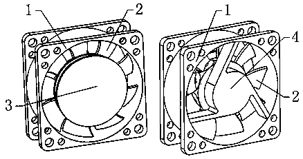
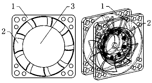
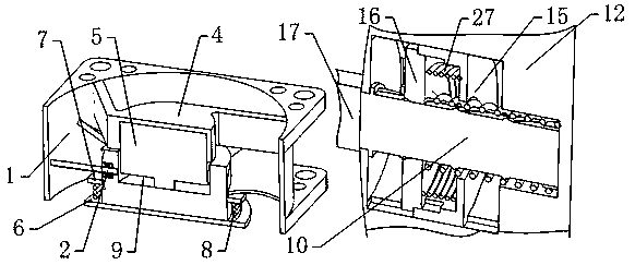
[0047] Such as figure 1 , 2 , 3, it includes the base 1, such as Figure 4 As shown, the bracket 4 fixed on the base 1, the driving motor 5 installed on the bracket 4, and the fan body 2 installed on the output shaft of the driving motor 5 are characterized in that: Figure 6 As shown, the fan body 2 is composed of a rotor 12 and fan blades 17, as Figure 7 As shown, one end of the rotor 12 has a nested circular groove 11, such as image 3 , 5 As shown, the rotor 12 is nested at one end of the drive motor 5 with the output shaft through the nesting circular groove 11, and the inner end surface of the nesting circular groove 11 is fixedly connected with the output shaft...


PUM


Abstract

The invention belongs to the technical field of fans and in particular relates to computer fan equipment with a back-flow preventing function. The computer fan equipment with the back-flow preventingfunction comprises a base, a bracket, a driving motor and a fan body, wherein the bracket is fixed on the base; the driving motor is mounted on the bracket; the fan body is mounted on an output shaftof the driving motor; due to a control device additionally arranged on the fan, the reliability of the fan is reduced, and the practicability is reduced; in particular during long-time use, a first spring in the fan can be damaged to fail to work, and fan blades cannot realize normal side swinging or returning; according to the computer fan equipment with the back-flow preventing function, in thisstate, the fan blades incapable of realizing normal side swinging swing to be opened under the driving of wind power; during returning, an adjusting ring is pressed down through a return spring, andthe adjusting ring drives the fan blades, which do not return, to swing to return; opening and returning functions of the corresponding fan blades are realized after the first spring is damaged; and in addition, through a disengaging structure of a slide block and a slide sleeve, it is guaranteed that the fan cannot be limited by thread fit between the slide block and a fixing shaft during swinging under the effect of wind in the case that the first spring is damaged.

Description

[0001] Technical field [0002] The invention belongs to the technical field of fans, and in particular relates to a computer fan device with backflow prevention. Background technique [0003] With the rapid upgrading of electronic products, the performance of computer hardware is becoming more and more powerful, which will inevitably lead to the generation of a lot of heat when these computer hardware with good performance are used, and the high temperature of computer hardware will greatly reduce it. Therefore, it is necessary to set up a heat dissipation mechanism to effectively dissipate heat to ensure that the hardware maintains high-performance operation for a long time. [0004] In a computer, a plurality of fans are usually installed to dissipate heat for electronic components in the electronic product. However, when some fans stop rotating due to a fault, the faulty fan will generate backflow of air flow, which will cause air flow turbulence and affect the heat dissi...

Claims


Application Information

Patent Timeline
Patent Type & Authority Applications(China)
IPC IPC(8): F04D25/08F04D25/16F04D29/38F04D29/36F04D27/00F04D29/64F04D29/66F04D29/70G06F1/20
CPCF04D25/08F04D25/166F04D27/002F04D29/36F04D29/388F04D29/646F04D29/666F04D29/667F04D29/703G06F1/20
Inventor 章丽
Owner 章丽
Why Eureka
Try Eureka