LED ceiling lamp with long service life

A LED chandelier with a long service life technology, which is applied in semiconductor devices of light-emitting elements, cooling/heating devices of lighting devices, lighting devices, etc., and can solve problems such as short service life of lamps, component damage, and cooling fins loaded on chandelier, and achieve Improve heat dissipation efficiency, speed up operation, and prolong service life

Inactive Publication Date: 2020-08-25
武汉钟码科技有限公司
View PDF5 Cites 7 Cited by
  • Summary
  • Abstract
  • Description
  • Claims
  • Application Information

AI Technical Summary

Problems solved by technology

[0003] When the LED chandelier is working, it will generate a lot of heat due to the thermal effect of the current. In order to pursue a high decorative effect, it is not suitable to load a large number of cooling fins on the chandelier. At the same time, the LED luminaire is sealed with epoxy resin.

Method used


Image

  • LED ceiling lamp with long service life
  • LED ceiling lamp with long service life

Examples


Embodiment 1

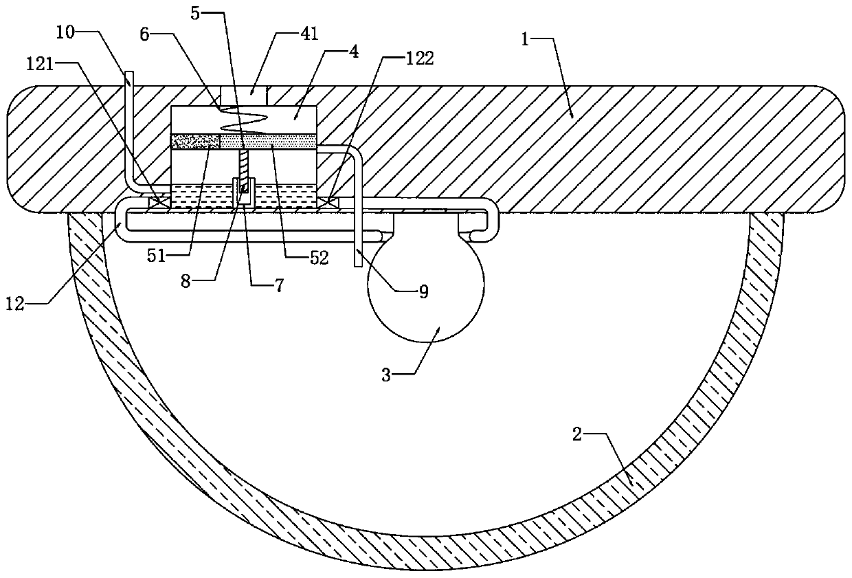
[0019] refer to figure 1 , an LED pendant lamp with long service life, comprising a mounting plate 1, a lamp housing 2 is installed at the lower end of the mounting plate 1, and an LED lamp body 3 is installed in the lamp housing 2.

[0020] The side wall of the mounting plate 1 is provided with a liquid storage tank 4, and a sliding plug 5 is sealed and slidably connected in the liquid storage tank 4. The liquid storage tank 4 is filled with cooling liquid, and the lamp housing 2 is embedded with a There is a condensing pipe 12, and the liquid inlet end and the liquid outlet end of the condensing pipe 12 are connected with the liquid storage tank 4, and the liquid inlet end and the liquid outlet end of the condensing pipe 12 are respectively installed with a first one-way The valve 121 and the second one-way valve 122, the liquid storage tank 4 is equipped with a driving device for driving the sliding plug 5 to move up and down.

[0021] It should be noted that the first one...

Embodiment 2

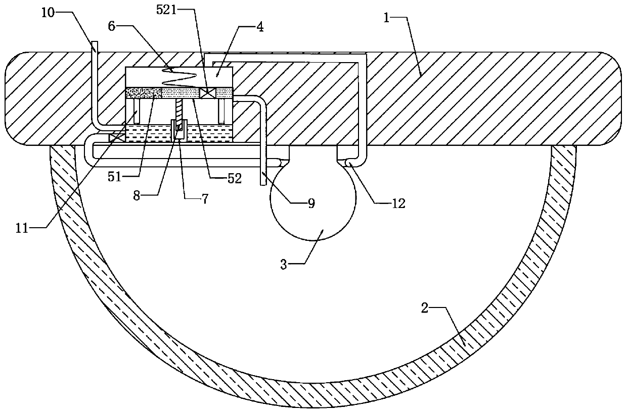
[0031] refer to figure 2 , different from Embodiment 1, the lower end of the sliding plug 5 is fixedly connected with a spoiler 11, the liquid outlet end of the condensation pipe 12 is fixedly connected with the inner top of the liquid storage tank 4, and the side wall of the heat conducting plug 52 is provided with a one-way Liquid outlet hole 521.

[0032] It should be noted that the one-way liquid outlet hole 521 only allows the cooling liquid to flow from above the slide plug 5 to below the slide plug 5 . Specifically, in the manufacturing process, the one-way liquid outlet function can be realized only by installing a one-way valve in the liquid outlet hole.

[0033] In this embodiment, during the rotation process of the sliding plug 5 under the action of the threaded sleeve 7 and the threaded rod 8, it will drive the spoiler 11 below to rotate, which can stir the cooling liquid in the liquid storage tank 4 and speed up the cooling process. The speed of heat loss in th...


PUM


Abstract

The invention discloses an LED ceiling lamp long in service life. The LED ceiling lamp comprises a mounting plate, and a lamp shell is mounted at the lower end of the mounting plate; an LED lamp bodyis installed in the lamp shell;aliquid storage tank is formed in the side wall of the mounting plate; a sliding plug is connected into the liquid storage tank in a sealing and sliding manner; and theliquid storage tank is filled with cooling liquid, a condensation pipe is embedded in the lamp shell, the liquid inlet end and the liquid outlet end of the condensation pipe both communicate with theinterior of the liquid storage tank, a first one-way valve and a second one-way valve are installed in the liquid inlet end and the liquid outlet end of the condensation pipe correspondingly, and a driving device for driving the sliding plug to move up and down is installed in the liquid storage tank. The driving device is arranged,when the temperature in the lamp body is too high, the driving device can operate, the sliding plug can move up and down in the liquid storage tank, under the flow limiting effect of the two one-way valves, cooling liquid is forced to flow in the condensation pipe in a one-way circulation mode, heat generated in the lamp body can be dissipated, damage to the lamp body by high temperature is avoided, and the service life of the lamp is prolonged.

Description

technical field [0001] The invention relates to the related technical field of LED lamps, in particular to an LED pendant lamp with long service life. Background technique [0002] LED chandelier refers to the lamps and lanterns that are hoisted on the indoor ceiling. In addition to providing lighting functions, it also has a good decorative effect. [0003] When the LED chandelier is working, it will generate a lot of heat due to the thermal effect of the current. In order to pursue a high decorative effect, it is not suitable to load a large number of cooling fins on the chandelier. At the same time, the LED luminaire is sealed with epoxy resin. As a result, it is difficult to dissipate the heat inside the lamp. After the heat accumulates, a higher temperature will be generated. The high temperature will cause damage to the components in the lamp body and accelerate the aging of the components, resulting in a shorter service life of the lamp. Accordingly, this application...

Claims


Application Information

Patent Timeline
IPC IPC(8): F21S8/06F21V29/51F21V29/70F21Y115/10
CPCF21S8/06F21V29/51F21V29/70F21Y2115/10
Inventor 李明
Owner 武汉钟码科技有限公司
Why Eureka
Try Eureka