Article detection system
A technology for item detection and item application in the field of communication, which can solve problems such as high cost, difference in reflection characteristics, and impact on the health of staff, and achieve the effect of a wide range of application scenarios
- Summary
- Abstract
- Description
- Claims
- Application Information
AI Technical Summary
Problems solved by technology
Method used
Image

Examples
Embodiment 1
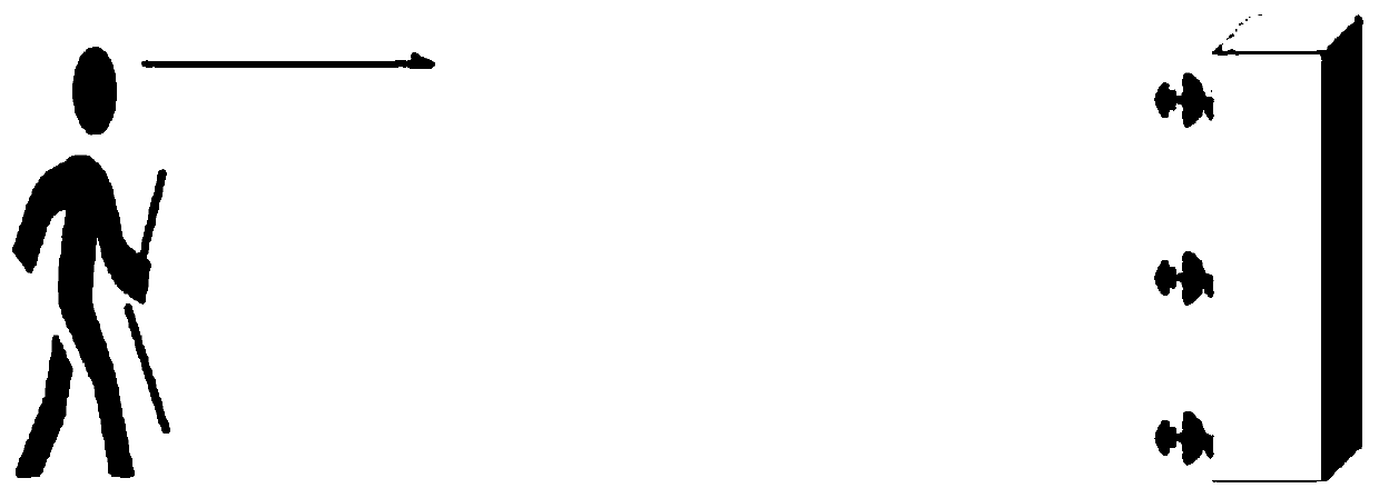
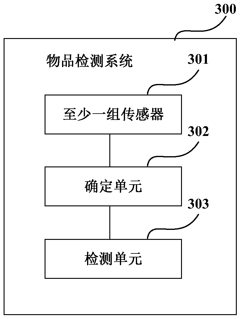
[0034] Embodiment 1 provides an article detection system; image 3 It is a schematic diagram of the composition of the object detection system, such as image 3 As shown, the system 300 includes: including at least one set of sensors 301, wherein one set of sensors is used to detect items carried in one direction of the moving body, each set of sensors 301 is respectively arranged on at least one side of the moving direction of the moving body, and For transmitting signals into space, the system 300 also includes:
[0035] A determination unit 302, which is used to determine the azimuth angle to be deployed of the first sensor in each group of sensors according to the preset effective detection area;
[0036] The detection unit 303 is used to extract the feature of the item carried by the mobile body according to the reflected signal received by each group of sensors deployed according to the azimuth angle, and determine the type of the item according to the feature. The refl...
Embodiment 2
[0079] Embodiment 2 of the present invention provides a method for detecting objects. Since the principle of solving problems of this method is similar to that of the system in Embodiment 1, its specific implementation can refer to the implementation of the device in Embodiment 1. The content is the same and will not be repeated Repeat instructions.
[0080] Figure 18 is a schematic diagram of an implementation of the object detection method in this embodiment, wherein the method is applied to an object detection system, and the system includes at least one set of sensors, wherein a set of sensors is used to detect the items carried in one direction of the moving body, The groups of sensors are respectively arranged on at least one side of the traveling direction of the moving body, and emit signals into the space.
[0081] Please refer to Figure 18 , the method includes:
[0082] Step 1801, determining the azimuth angle to be deployed of the first sensor in each group of...
Embodiment 3
[0092] Embodiment 3 of the present invention provides an object detection device. Since the problem-solving principle of the device is similar to the method in Embodiment 2, its specific implementation can refer to the implementation of the method in Embodiment 2. The content is the same and will not be repeated Repeat instructions.
[0093] Figure 19 It is a schematic diagram of an implementation of the article detection device of this embodiment, wherein the article detection device is connected to at least one set of sensors, wherein one set of sensors is used to detect items carried in one direction of the moving body, and each set of sensors is respectively It is arranged on at least one side of the traveling direction of the mobile body, and emits signals into the space.
[0094] Please refer to Figure 19 , the device consists of:
[0095] A determination unit 1901, configured to determine the azimuth angle to be deployed of the first sensor in each group of sensors...
PUM
 Abstract
Description
Claims
Application Information
 - Generate Ideas
- Intellectual Property
- Life Sciences
- Materials
- Tech Scout
- Unparalleled Data Quality
- Higher Quality Content
- 60% Fewer Hallucinations
Browse by: Latest US Patents, China's latest patents, Technical Efficacy Thesaurus, Application Domain, Technology Topic, Popular Technical Reports.
© 2025 PatSnap. All rights reserved.Legal|Privacy policy|Modern Slavery Act Transparency Statement|Sitemap|About US| Contact US: help@patsnap.com