Yaw angle measuring system and method based on multiple MEMS inertial sensors and flight control system

An inertial sensor and measurement system technology, applied in the field of yaw angle measurement, can solve problems such as yaw angle measurement errors, scene restrictions, and data errors, and achieve the effects of low cost, wide application scene range, and high reliability

Active Publication Date: 2021-07-16
北京海淀中科计算技术转移中心
View PDF7 Cites 2 Cited by
  • Summary
  • Abstract
  • Description
  • Claims
  • Application Information

AI Technical Summary

Problems solved by technology

Option 1 uses a magnetometer, and Option 3 requires GNSS signals, both of which mean that the attitude measurement system will be affected by the outside (the inertial sensor is not affected by any external signal of the carrier, it is only affected by the movement of the carrier itself, External signals include GNSS signals, magnetic fields, 5G signals, etc.), which cannot be used in many scenarios such as underground power pipe corridors, high-voltage power lines, and near magnetic objects. The large magnetic field interference in these places will make the magnetic force in Scheme 1 The data measured by the meter is wrong, which leads to the wrong measurement of the yaw angle
Similarly, in many application scenarios, such as underground utility corridors, it is difficult to obtain stable and reliable GNSS signals, and scheme 3 cannot be applied
Therefore, the application of scheme 1 and scheme 3 has many scene restrictions
[0008] (2) The tactical-grade gyroscope used in Scheme 2 is expensive, ranging from a few hundred yuan to tens of thousands of yuan, and does not have market promotion value

Method used


Image

  • Yaw angle measuring system and method based on multiple MEMS inertial sensors and flight control system
  • Yaw angle measuring system and method based on multiple MEMS inertial sensors and flight control system
  • Yaw angle measuring system and method based on multiple MEMS inertial sensors and flight control system

Examples


Embodiment Construction

[0046] The following will clearly and completely describe the technical solutions in the embodiments of the present invention with reference to the accompanying drawings in the embodiments of the present invention. Obviously, the described embodiments are only some, not all, embodiments of the present invention. Based on the embodiments of the present invention, other embodiments obtained by persons of ordinary skill in the art without making creative efforts all belong to the protection scope of the present invention.

[0047] In the description of the present invention, it should be noted that the orientation or positional relationship indicated by the terms "vertical", "upper", "lower", "horizontal" etc. is based on the orientation or positional relationship shown in the drawings, and is only In order to facilitate the description of the present invention and simplify the description, it does not indicate or imply that the device or element referred to must have a specific o...


PUM


Abstract

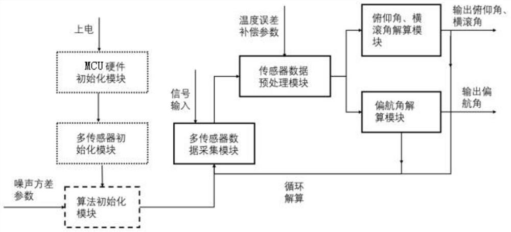
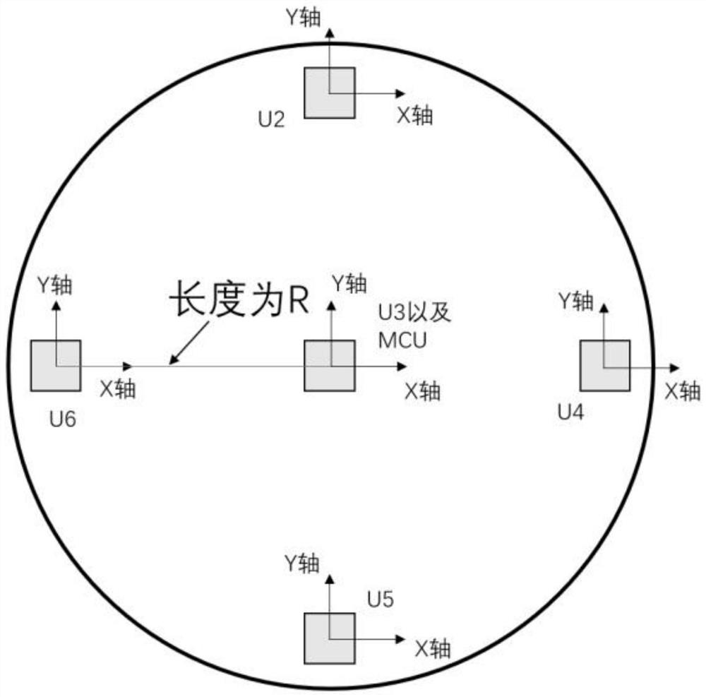
The invention provides a yaw angle measurement system and method based on multiple MEMS inertial sensors and a flight control system. The yaw angle measurement system comprises an initialization module, a sensor data acquisition module, a sensor data preprocessing module, a yaw angle calculation module and a pitch angle and roll angle calculation module. The initialization module is used for hardware initialization, algorithm initialization and multi-sensor initialization; the sensor data acquisition module firstly selects inertial sensors and reads measurement values of a gyroscope, an accelerometer and a temperature sensor of each inertial sensor one by one; the sensor data preprocessing module preprocesses original measurement data; the yaw angle resolving module is used for obtaining an accurate yaw angle through integral operation according to the accurate Z-axis angular velocity obtained through calculation by a filtering algorithm; and the pitch angle and roll angle resolving module is used for resolving a pitch angle and a roll angle. The system does not depend on a magnetometer or a GNSS signal, is not influenced by the change of an external magnetic field, and is wide in application scene range and low in cost.

Description

technical field [0001] The invention relates to a yaw angle measurement technology, in particular to a yaw angle measurement system, method and flight control system based on multiple MEMS inertial sensors. Background technique [0002] Attitude angle includes pitch angle, roll angle, and yaw angle. In the civilian field, low-cost but noisy low-end MEMS (micro-electromechanical systems) inertial sensors (inertial sensors include accelerometers and gyroscopes) are generally used to solve Attitude angle, pitch angle, and roll angle can be calculated by fusing the measurement data of a three-axis MEMS accelerometer and a three-axis MEMS gyroscope. For the calculation of the yaw angle, the existing technical solutions mainly include the following three types: [0003] 1. Use a three-axis MEMS gyroscope and a three-axis MEMS magnetometer to solve the yaw angle. First use the Z-axis angular velocity measured by the gyroscope (the carrier space coordinate system is composed of XY...

Claims


Application Information

Patent Timeline
Patent Type & Authority Applications(China)
IPC IPC(8): G05D1/08G05D1/10G01C21/18
CPCG05D1/0808G05D1/101G01C21/18
Inventor 陈冰冰阳建仁温治强利剑清陈盛宏
Owner 北京海淀中科计算技术转移中心
Why Eureka
Try Eureka