Gate drive circuit and drive method thereof

A gate drive circuit and drive method technology, applied in static memory, instruments, static indicators, etc., can solve problems such as waste of power consumption, insufficient charging time, and inability to develop and mass-produce products, reducing drive power consumption, The effect of increasing the charging time

Inactive Publication Date: 2020-08-25
NANJING CEC PANDA LCD TECH
View PDF5 Cites 2 Cited by
  • Summary
  • Abstract
  • Description
  • Claims
  • Application Information

AI Technical Summary

Problems solved by technology

[0005] This kind of gate scanning driving circuit will bring the following disadvantages: ① The charging time of sequentially scanning each row of pixels is fixed, and the charging time will be insufficient when it is applied to products with high refresh rate and high resolution, resulting in insufficient pixel charging rate, and the product cannot be developed. and mass production; ②Each frame will repeatedly charge each pixel, resulting in waste of power consumption

Method used


Image

  • Gate drive circuit and drive method thereof
  • Gate drive circuit and drive method thereof
  • Gate drive circuit and drive method thereof

Examples


Embodiment Construction

[0032] In order to more clearly illustrate the embodiments of the present invention or the technical solutions in the prior art, the specific implementation manners of the present invention will be described below with reference to the accompanying drawings. Obviously, the accompanying drawings in the following description are only some embodiments of the present invention, and those skilled in the art can obtain other accompanying drawings based on these drawings and obtain other implementations.

[0033] In order to make the drawing concise, each drawing only schematically shows the parts related to the present invention, and they do not represent the actual structure of the product. In addition, to make the drawings concise and easy to understand, in some drawings, only one of the components having the same structure or function is schematically shown, or only one of them is marked. Herein, "a" not only means "only one", but also means "more than one".

[0034] The techni...


PUM


Abstract

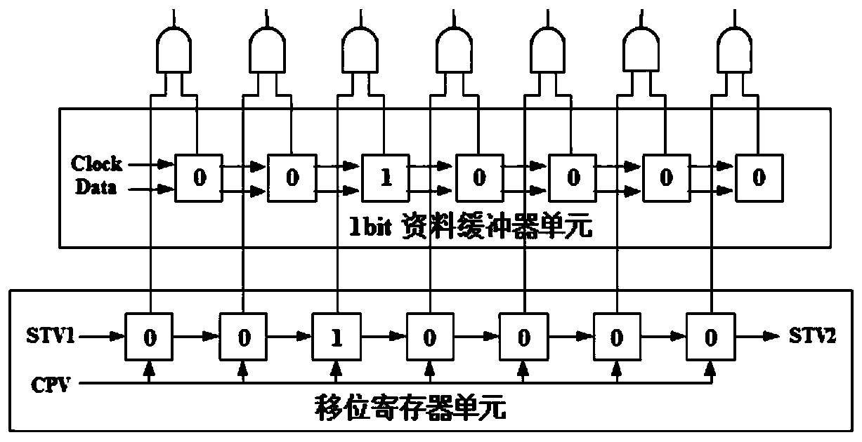
The invention provides a grid driving circuit and a driving method thereof, and relates to the technical field of panel display. A grid driving circuit is connected with a time schedule controller andcomprises a shift register unit and a data buffer unit, and the data buffer unit is used for storing a temporary memory numerical value of a horizontal row of pixels needing to be updated for each frame of data; when each frame of data is ended, the time sequence controller compares the next frame of data to be updated with the currently input frame of data to obtain a temporary memory numericalvalue of a horizontal row of pixels needing to be updated of the corresponding next frame of data, and inputs a data signal and a clock signal to the data buffer unit for numerical value storage; a numerical value in the shift register unit and a numerical value in the data buffer unit are input into the level shifter unit after passing through an AND gate, and the level shifter unit outputs a corresponding high-frequency pulse signal through the output buffer unit to control the opening time of a corresponding grid; in each frame of grid scanning, pixels needing to be updated are charged, andpixels needing not to be updated are not charged.

Description

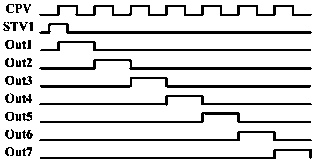
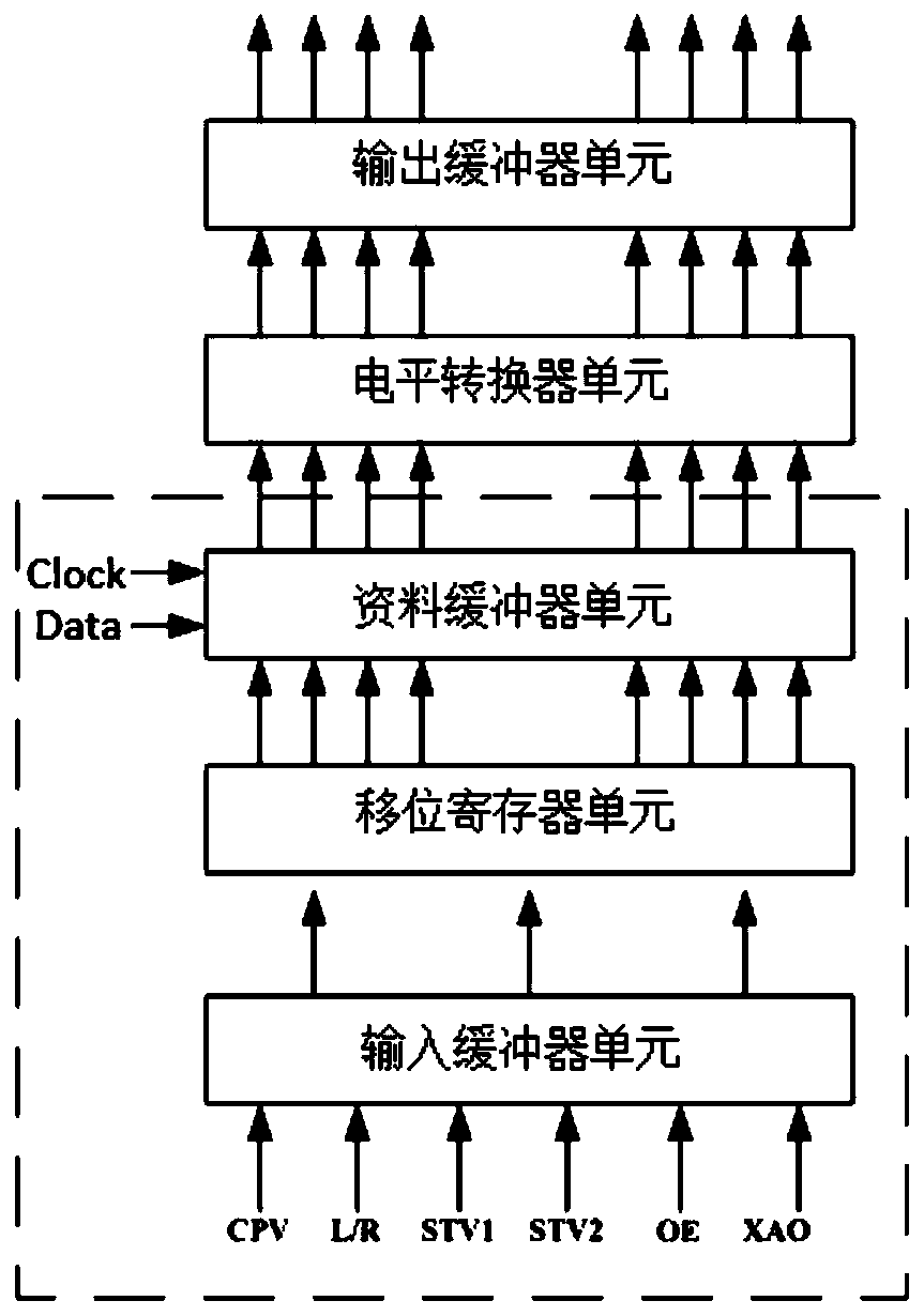
technical field [0001] The invention belongs to the technical field of panel display, and in particular relates to a gate drive circuit and a drive method thereof. [0002] technical background [0003] In a traditional gate drive circuit, the gates are turned on line by line from top to bottom or bottom to top in each frame, the scanning frequency is fixed, and the charging time of each horizontal line to the pixels is fixed. [0004] The conventional gate drive circuit adopts a sequential scanning method, and the shift register unit inside the gate drive circuit module inputs various control signals (CPV, L / R, etc.), figure 1 It is the driving timing diagram of the existing gate driving circuit, wherein the STV1 signal provides the signal for opening the first line of the gate, and the CPV signal output by the timing controller TCON changes the register value in the shift register at its rising edge. On each rising edge of the CPV signal, the value 1 in the shift register ...

Claims


Application Information

Patent Timeline
Patent Type & Authority Applications(China)
IPC IPC(8): G09G3/20G11C19/28
CPCG09G3/20G11C19/28G09G2310/0286G09G2330/021
Inventor 蓝东鑫李杰
Owner NANJING CEC PANDA LCD TECH
Why Eureka
Try Eureka