Portable lifting device for building power tower

A portable, power tower technology, applied in the field of electric power, can solve problems such as safety risk efficiency, inconvenient operation, high-voltage line drop, etc., and achieve the effect of improving safety, convenient operation and strong applicability

Active Publication Date: 2020-08-25
邵阳市大通电力设备制造有限公司
View PDF6 Cites 1 Cited by
  • Summary
  • Abstract
  • Description
  • Claims
  • Application Information

AI Technical Summary

Problems solved by technology

[0004] Aiming at the deficiencies of the prior art, the present invention provides a portable lifting device for building a power tower, which solves the problem that the geographical conditions mentioned in the background technology cannot make the operation inconvenient for the crane to lift the high-voltage line, and the high-voltage line falls when the high-voltage line is pulled by a rope. Problems that cause security risks and low efficiency

Method used


Image

  • Portable lifting device for building power tower
  • Portable lifting device for building power tower
  • Portable lifting device for building power tower

Examples


Embodiment 1

[0031] The following will clearly and completely describe the technical solutions in the embodiments of the present invention with reference to the accompanying drawings in the embodiments of the present invention. Obviously, the described embodiments are only some, not all, embodiments of the present invention. Based on the embodiments of the present invention, all other embodiments obtained by persons of ordinary skill in the art without making creative efforts belong to the protection scope of the present invention.

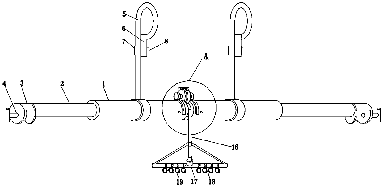
[0032] Such as Figure 1-10As shown, a portable lifting device for building a power tower includes two load-bearing rods 1, the two ends of the load-bearing rods 1 are movably connected with auxiliary rods 2, and the auxiliary rods 2 are threaded in the threaded grooves opened on one side of the load-bearing rod 1 , when the auxiliary pole 2 is turned clockwise or counterclockwise, the two auxiliary poles 2 can approach or move away from each other, so that th...

Embodiment 2

[0040]When using this device to install the normal stretching high-voltage line: turn the auxiliary pole 2, adjust the device to a suitable length, clamp the block 3 on the auxiliary beam of the electric tower, and adjust the fastening bolt 4 so that the fastening bolt 4 is in line with the electric tower The auxiliary beam is clamped, and then the load-bearing steel wire 5 is set on the transverse channel steel above the power tower, and one end of the clamping ring 7 passes through the circular groove opened by the threaded block 6, and the fastening nut 8 is threaded to the clamping ring 7. One end, and tighten the threaded block 6, so that the clamping ring 7 and the fastening nut 8 can be firmly clamped. Connect and place on the ground, fix the high-voltage wires in a plurality of high-voltage wire fixing rings 19, and then fasten the two U-shaped clips 11 on the two load-bearing rods 1 respectively, and the two U-shaped clips 10 are connected by the elastic clips 10 Clip...

Embodiment 3

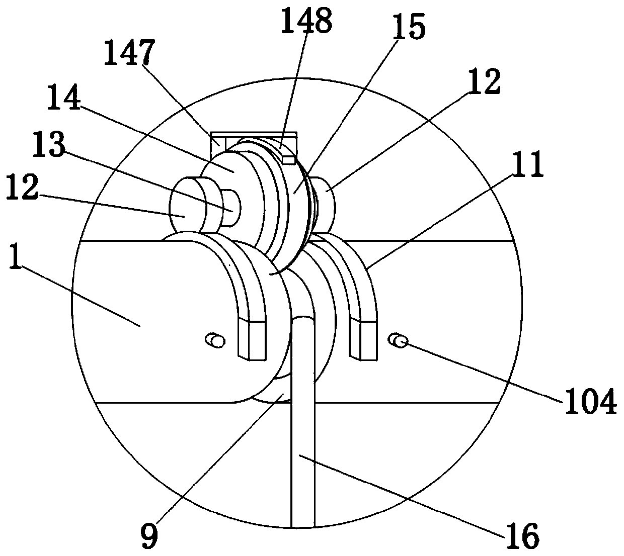
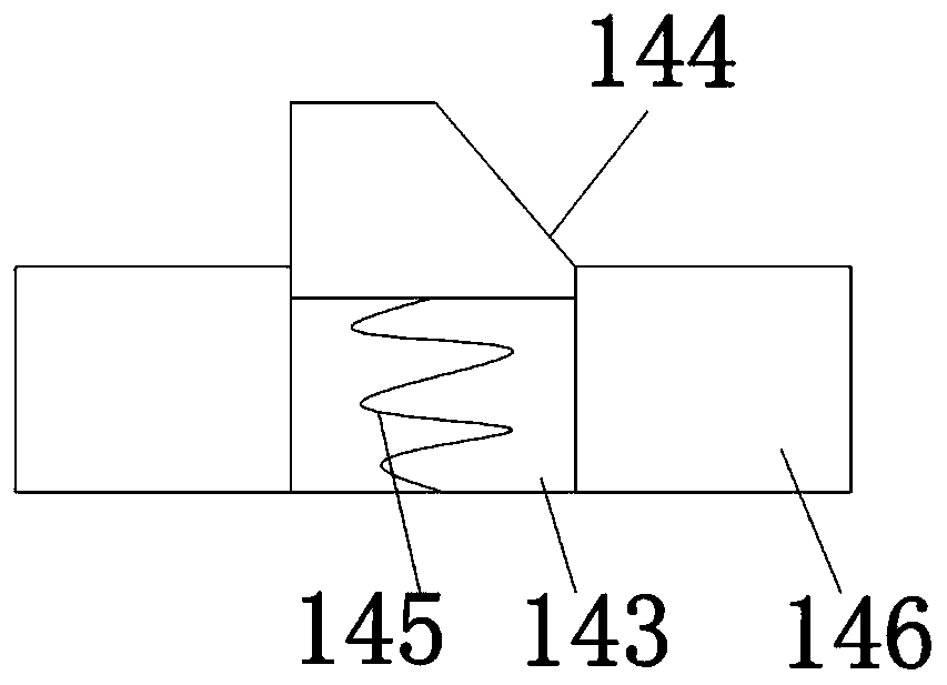
[0042] When the device is installed to cause the stay rope 16 to fall due to an accident: when the stay rope 16 slides down due to an accident, such as insufficient pulling force of the stay rope 16, the stay rope 16 drives the locking wheel 153 to drop along the stay rope 16 The direction of the rotation, the clamping wheel 153 drives the internal snap ring 151 to rotate, the fixed teeth 153 inside the snap ring 151 are in direct contact with the movable teeth 144, the fixed teeth 153 and the movable teeth 144 block each other, and the movable teeth 144 will not enter the movable groove 143, the snap ring 151 drives the rotating shaft 146 to rotate through the fixed teeth 153 and the movable teeth 144, and the rotating shaft 146 drives the fixed shaft 142, the limit gear sleeve 14, the support block 147, and the brake disc 148 to rotate , until the brake disc 148 rotates with the limit tooth sleeve 14 and snaps into the gap between the limit tooth sleeve 14 and the one-way lim...


PUM


Abstract

The invention discloses a portable lifting device for building a power tower. The device comprises two bearing bars, the two ends of the bearing rods are movably connected with auxiliary rods; ends ofthe auxiliary rods are fixedly connected with clamping blocks and fastening screw rods; load-bearing steel wires sleeve the bearing rods; a pulley and a rotating rod are arranged between the bearingrods; one end of the rotating rod is fixedly connected with a limiting gear sleeve; the limiting gear sleeve is sleeved with a one-way limiting wheel; the limiting gear sleeve comprises a circular sleeve and a fixed shaft at the axis; a supporting block and a brake disc are arranged above the two limiting gear sleeves, a pull rope penetrates through the position between the pulley and the one-waylimiting wheel, one end of the pull rope is movably connected with a bearing frame, the bearing frame is sleeved with a rotating ring, and the bottom of the rotating ring is fixedly connected with a high-voltage wire fixing ring. The device solves the problems that a crane cannot lift a high-voltage line due to geographical condition limitation, the operation is inconvenient, the high-voltage linefalls off when a rope is used for pulling the high-voltage line, safety risks are caused, and the efficiency is low.

Description

technical field [0001] The invention relates to the field of electric power technology, in particular to a portable lifting device for building electric power towers. Background technique [0002] In the high-voltage line transmission technology, the high-voltage line is generally transmitted by a power tower, and the height of the power tower is generally as high as several hundred meters. After the power tower is built, the high-voltage line needs to be built, and the common way to build a high-voltage line is: a lower height The power tower uses a crane to lift the high-voltage line to a fixed installation place; the taller power tower uses ropes to lift and install each high-voltage line separately. There are at least the following deficiencies in the above-mentioned process of hoisting high-voltage lines: First, when using a crane to lift high-voltage lines for power towers with low heights, on the one hand, multiple high-voltage lines are hoisted at one time, which may...

Claims


Application Information

Patent Timeline
IPC IPC(8): H02G1/04H02G7/20
CPCH02G1/04H02G7/20
Inventor 张华艳
Owner 邵阳市大通电力设备制造有限公司
Why Eureka
Try Eureka