Infrared space camera static transfer function test system and test method

A technology of space camera and static transmission, applied in the field of space optics, to achieve a wide range of engineering application prospects and improve the effect of test accuracy

Active Publication Date: 2020-08-25
CHANGCHUN INST OF OPTICS FINE MECHANICS & PHYSICS CHINESE ACAD OF SCI
View PDF4 Cites 2 Cited by
  • Summary
  • Abstract
  • Description
  • Claims
  • Application Information

AI Technical Summary

Problems solved by technology

[0003] In order to solve the problem of relatively large errors in the static transmission test of the existing medium-wave / long-wave infrared space optical camera, the present invention provides a black body with a low-temperature baffle as a radiation source, and uses an infrared radiation source composed of an infrared target and a low-temperature collimator. Space camera MTF test system and test method

Method used


Image

  • Infrared space camera static transfer function test system and test method
  • Infrared space camera static transfer function test system and test method
  • Infrared space camera static transfer function test system and test method

Examples


specific Embodiment approach 1

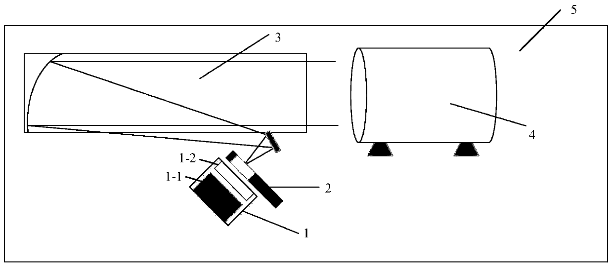
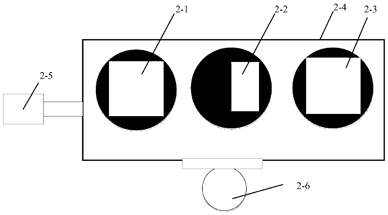
[0030] Specific implementation mode 1. Combination Figure 1 to Figure 4 Describe this embodiment, an infrared space camera static transfer function test system, which is composed of a black body radiation source 1, a target assembly 2 and an infrared collimator 3 arranged in a vacuum low temperature environment simulation device 5, and all of them can be tested in a vacuum low temperature environment. down to work. Among them, the black body radiation source 1 is equipped with a low-temperature baffle that can be opened and closed at a working temperature of less than 100K, and a target assembly 2 is placed on the focal plane of the infrared collimator 3, and three types of targets are installed on the target assembly 2, which are light holes respectively. Target 2-1, low spatial frequency target 2-2 and Nyquist frequency target 2-3 are used to test the thermal radiation, object space modulation and image space modulation of collimator and space camera optical system respecti...

specific Embodiment approach 2

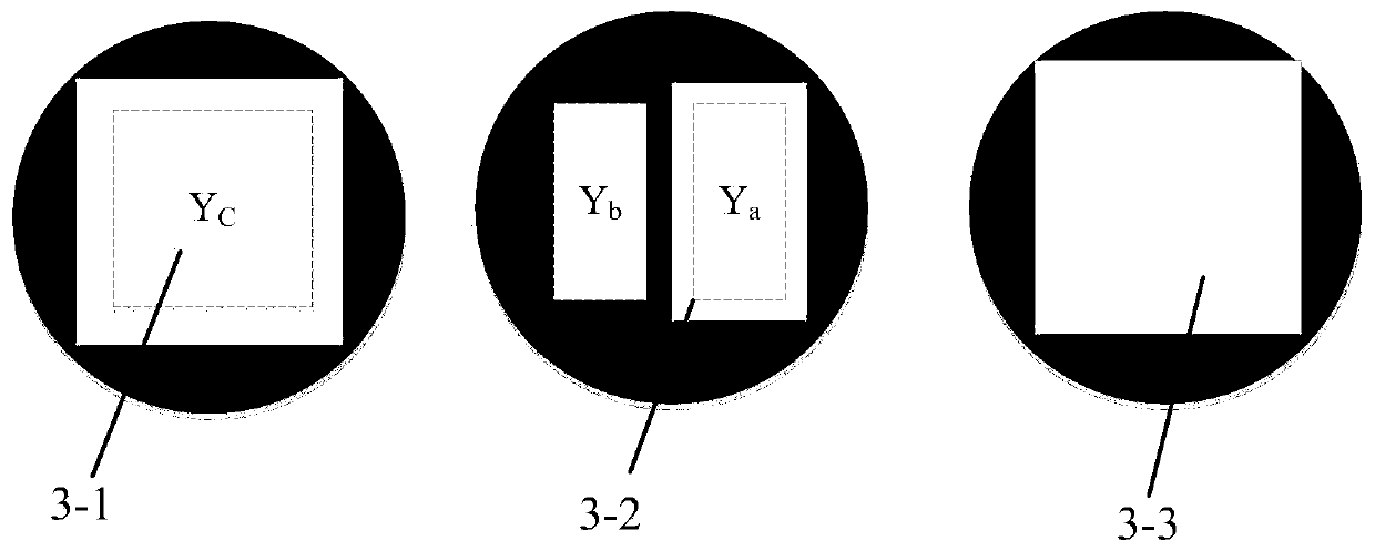
[0034] Specific embodiment two, combine Figure 1 to Figure 4 Describe this embodiment, this embodiment is the test method of a static transfer function test system for an infrared space camera described in the first embodiment, in the MTF test, first switch the target component to the low spatial frequency target 2-2, set The temperature of the vacuum low-temperature blackbody 1-1 makes the gray value of the image corresponding to the light hole unsaturated, and obtains the low spatial frequency target image;

[0035] Keep the temperature of the vacuum low-temperature blackbody 1-1 unchanged, switch to the Nyquist frequency target 2-3, and obtain the image of the Nyquist frequency target;

[0036] Then switch to the through-hole target 2-1, cut the low-temperature baffle 1-2 in front of the blackbody radiation source into the light path, block the low-temperature baffle 1-2 in the vacuum low-temperature blackbody 1-1, and acquire the image of the through-hole target.

[0037...


PUM

PropertyMeasurementUnit
Thicknessaaaaaaaaaa

Abstract

The invention discloses an infrared space camera static transfer function test system and test method, relates to the field of space optics, and solve the problem that large errors exist in an conventional medium-wave / long-wave infrared space optical camera static transfer function test. A MTF testing system is composed of a blackbody radiation source, a target assembly and an infrared collimator,a low-temperature baffle smaller than 100 K is arranged in front of the blackbody radiation source, and the MTF testing process comprises: switching the target assembly into a low-space-frequency target to obtain an object space modulation degree; switching the target assembly into a Nyquist frequency target to obtain an image space modulation degree; then enabling a low-temperature baffle in front of the blackbody radiation source to shield the blackbody, switching the target assembly to a through hole target state, obtaining an image for calculating gray values generated by heat radiationof the collimator and the camera optical system; and calculating the MTF of the infrared camera by using the obtained image data. According to the method, the object space modulation degree is accurately tested, the MTF true value is objectively obtained, and the imaging quality of the space camera can be more objectively evaluated.

Description

technical field [0001] The invention relates to the field of space optics, in particular to a static transfer function test system and test method for an infrared space camera. Background technique [0002] With the development of space optical remote sensors, the aperture of medium-wave or long-wave infrared space cameras (referred to as "infrared space cameras") has gradually increased from 0.5m to 1m, 1.5m, and even greater than 2.0m. The MTF of infrared space cameras Testing is an important technical index to evaluate its imaging performance. Therefore, MTF testing must be carried out during its development and before delivery and acceptance. Infrared space cameras are greatly affected by laboratory thermal radiation, especially to reduce the impact of thermal radiation on optical-mechanical systems. Influenced by imaging performance, the temperature of the optomechanical system is generally below zero, so the MTF test of the infrared space camera needs to be carried out...

Claims


Application Information

Patent Timeline
IPC IPC(8): H04N17/00
CPCH04N17/002
Inventor 李宪圣刘洪兴孙斌陈长征聂婷
Owner CHANGCHUN INST OF OPTICS FINE MECHANICS & PHYSICS CHINESE ACAD OF SCI
Why Eureka
Try Eureka