
Delay lighting system

A technology of a lighting system and an energy storage unit, applied in the lighting field, can solve problems such as inability to realize delayed lighting, and achieve the effect of improving lighting experience

Pending Publication Date: 2020-08-25
SENGLED CO LTD
View PDF3 Cites 2 Cited by
  • Summary
  • Abstract
  • Description
  • Claims
  • Application Information

AI Technical Summary

Problems solved by technology

[0004] In actual use, when the lighting circuit of the LED lighting device is disconnected, the external power grid will no longer supply power to the LED lighting device, and the LED lighting device will immediately go out at this time, and the delayed lighting cannot be realized.

Method used


Image

  • Delay lighting system
  • Delay lighting system
  • Delay lighting system

Examples


Embodiment Construction

[0055] In order to make the purposes, technical solutions and advantages of the exemplary embodiments of the present application clearer, the technical solutions in the exemplary embodiments of the present application will be clearly and completely described below in conjunction with the accompanying drawings in the exemplary embodiments of the present application. , the described exemplary embodiments are only some of the embodiments of the present application, but not all of the embodiments.

[0056] The time-delay lighting system provided by the embodiment of the present application is applicable to any lighting device, for example, it is suitable for LED lighting device.

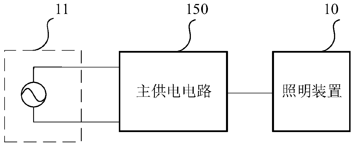
[0057] figure 1 It is a schematic diagram of an existing lighting system. The existing lighting system includes a main power supply circuit 150 and a lighting device 10 , and the main power supply circuit 150 is connected to the mains 11 and the lighting device 10 respectively. When the main power suppl...


PUM


Abstract

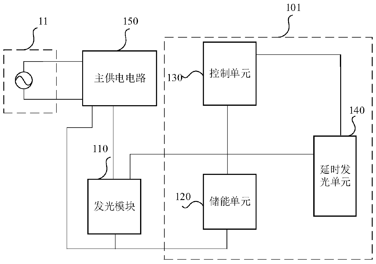
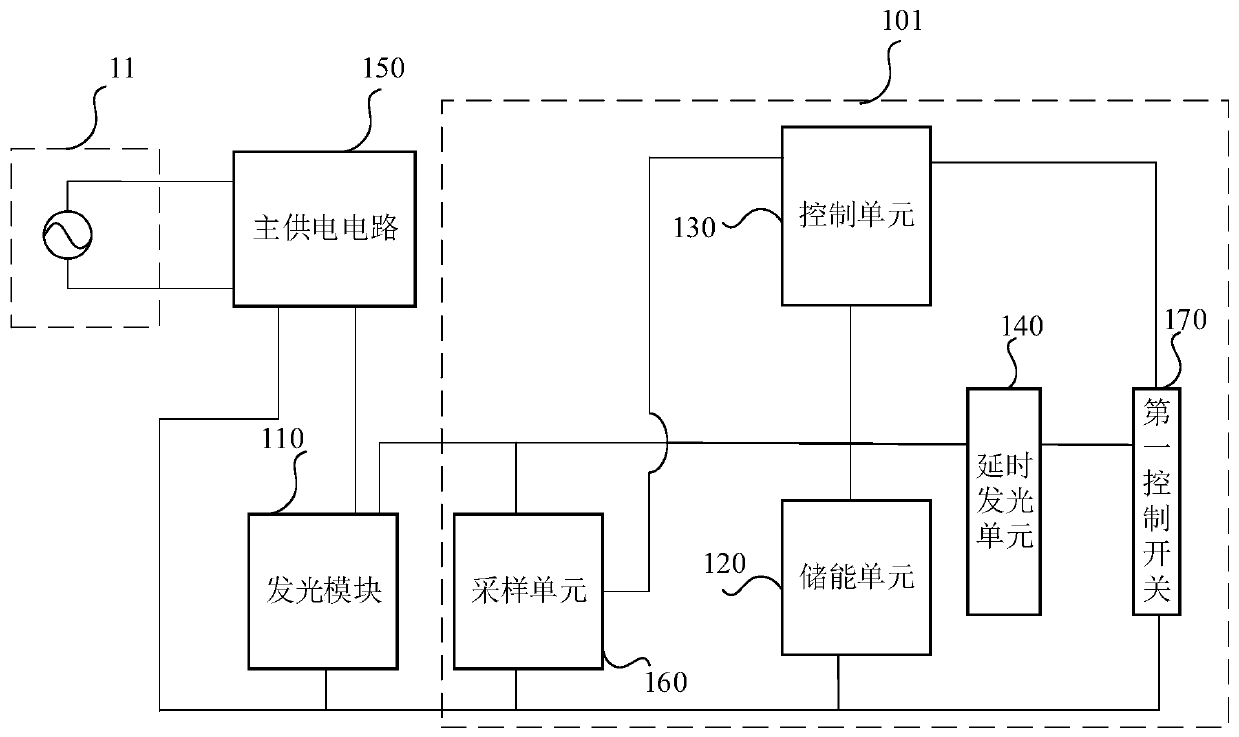
The embodiment of the invention discloses a delay lighting system, which comprises a light emitting module, an energy storage unit, a control unit, a delay light emitting unit and a main power supplycircuit connected with the light emitting module. The control unit is connected with the energy storage unit, the light emitting module and the delay light emitting unit respectively; the energy storage unit is used for storing electric energy of mains supply into the energy storage unit when the main power supply circuit supplies power to the light emitting module, and the control unit is used for controlling the energy storage unit to supply power to the delay light emitting unit when the main power supply circuit stops supplying power to the light emitting module, so that the delay light emitting unit emits light. The delay lighting system can realize delay lighting of the delay light emitting module when the light emitting module stops lighting.

Description

technical field [0001] The present application relates to the technical field of lighting, in particular to a time-delay lighting system. Background technique [0002] Light-emitting diode (Light Emitting Diode, LED) lighting device uses LED as a light source. LED is a solid-state semiconductor device that can convert electrical energy into visible light. Its heart is a semiconductor chip, and one end of the chip is attached to a bracket. , one end is the negative pole, and the other end is connected to the positive pole of the power supply, so that the entire chip is encapsulated by epoxy resin. [0003] LED lighting devices have the following characteristics: long life; good applicability, a single LED is small in size and can be made into any shape; short response time, which is ns (nanosecond) level response time, while ordinary lamps are ms (milliseconds) High-level response time; environmental protection, no harmful metals, easy recycling of waste; gorgeous color, pur...

Claims


Application Information

Patent Timeline
IPC IPC(8): H05B45/30H05B45/10
CPCH05B45/30H05B45/10Y02B20/40H05B47/16H05B45/34H05B45/3725
Inventor 万叶华蔡余良
Owner SENGLED CO LTD
Learn More