Steel wire rope cutting device

A cutting device and wire rope technology, which is applied in the field of wire rope cutting, can solve problems such as potential safety hazards, increased use costs, and damage to cutting pieces, and achieve the effects of avoiding high temperature, improving safety factor, and avoiding wire rope deformation

Inactive Publication Date: 2020-08-28
唐山天天安科技有限公司
View PDF5 Cites 3 Cited by
  • Summary
  • Abstract
  • Description
  • Claims
  • Application Information

AI Technical Summary

Problems solved by technology

[0003] During the cutting process of the existing steel wire rope, the steel wire rope will slide, causing the cutting section of the steel wire rope to be uneven, reducing the cutting quality of the steel wire rope, reducing the production efficie

Method used


Image

  • Steel wire rope cutting device
  • Steel wire rope cutting device
  • Steel wire rope cutting device

Examples


Embodiment 1

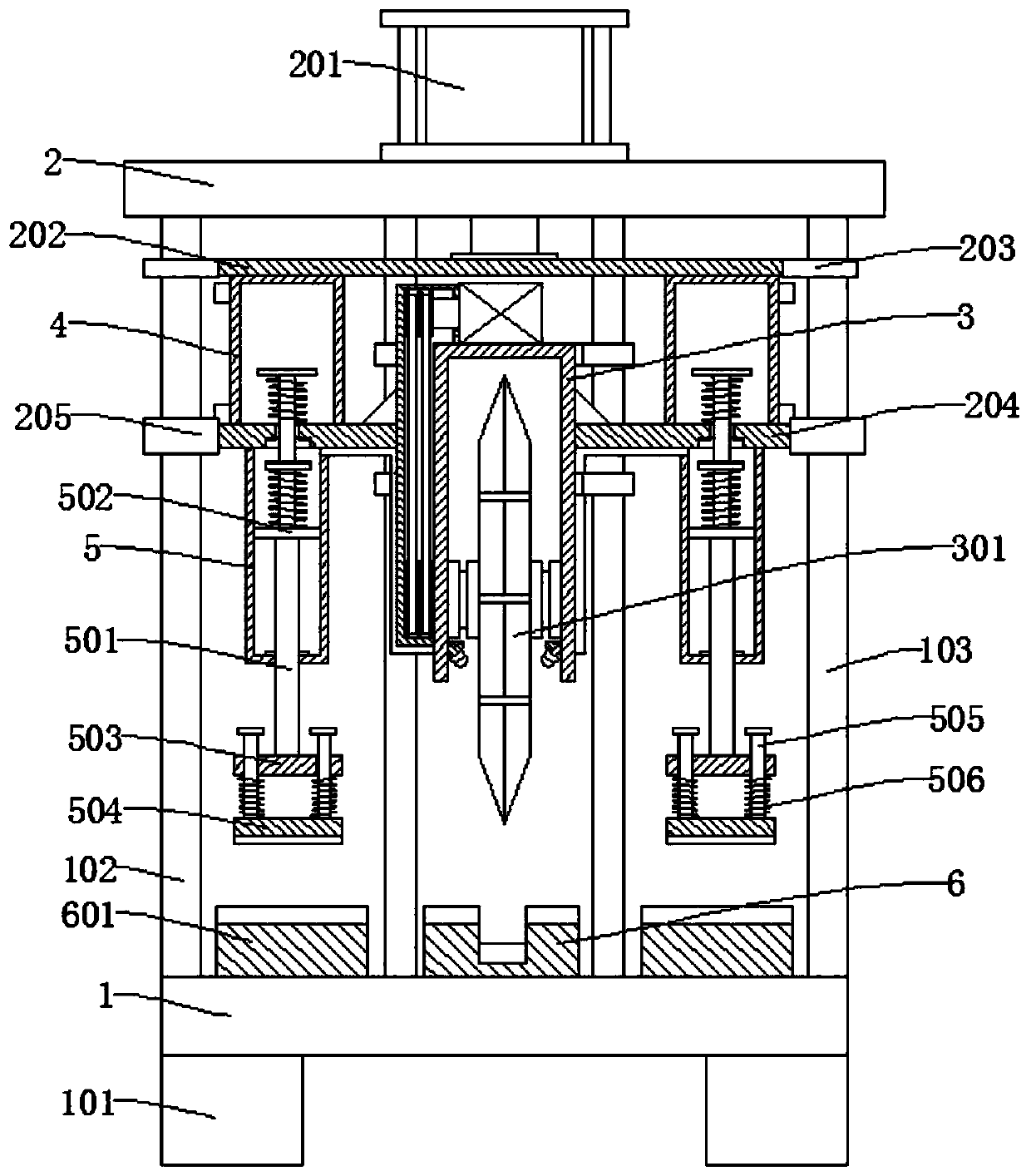
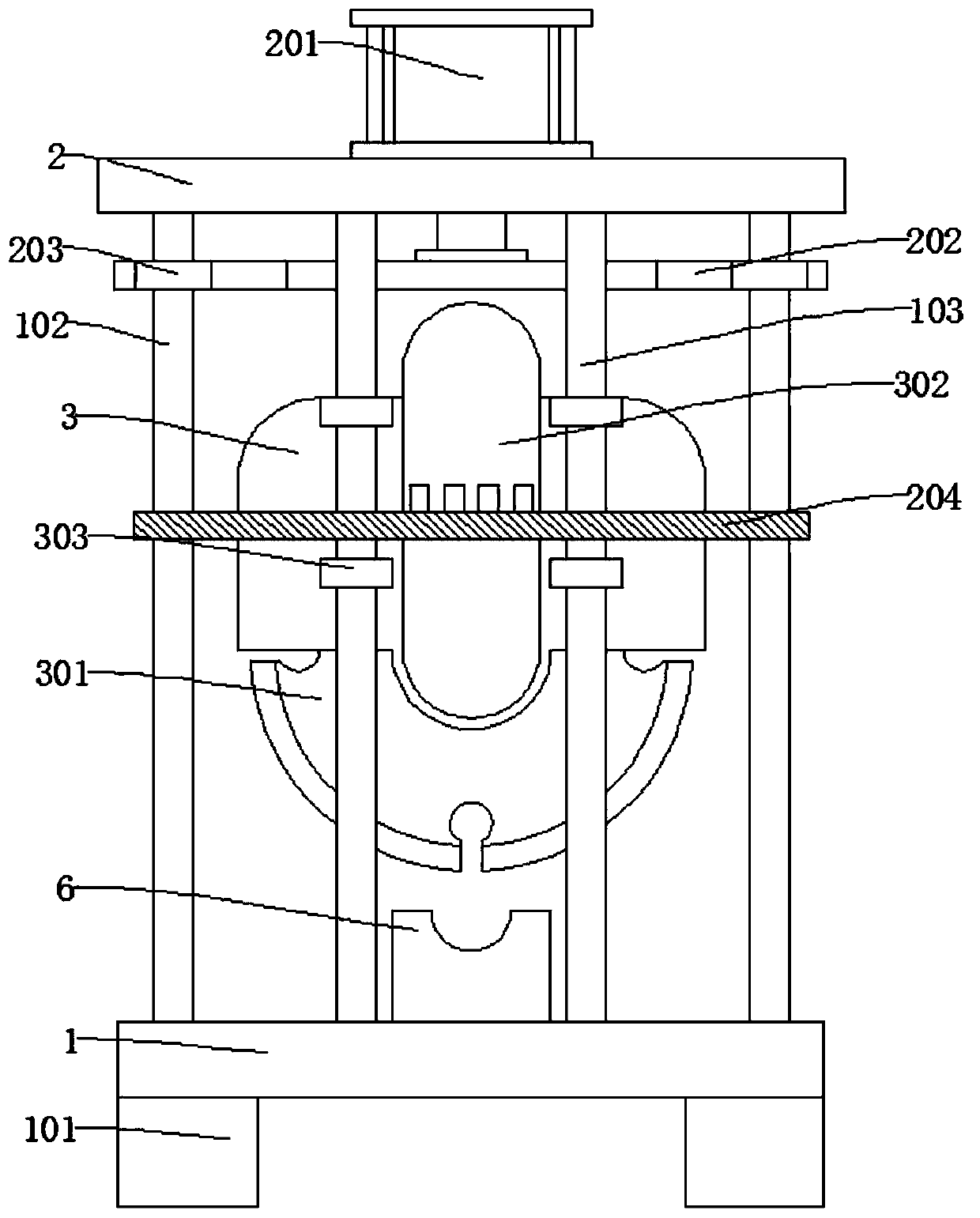
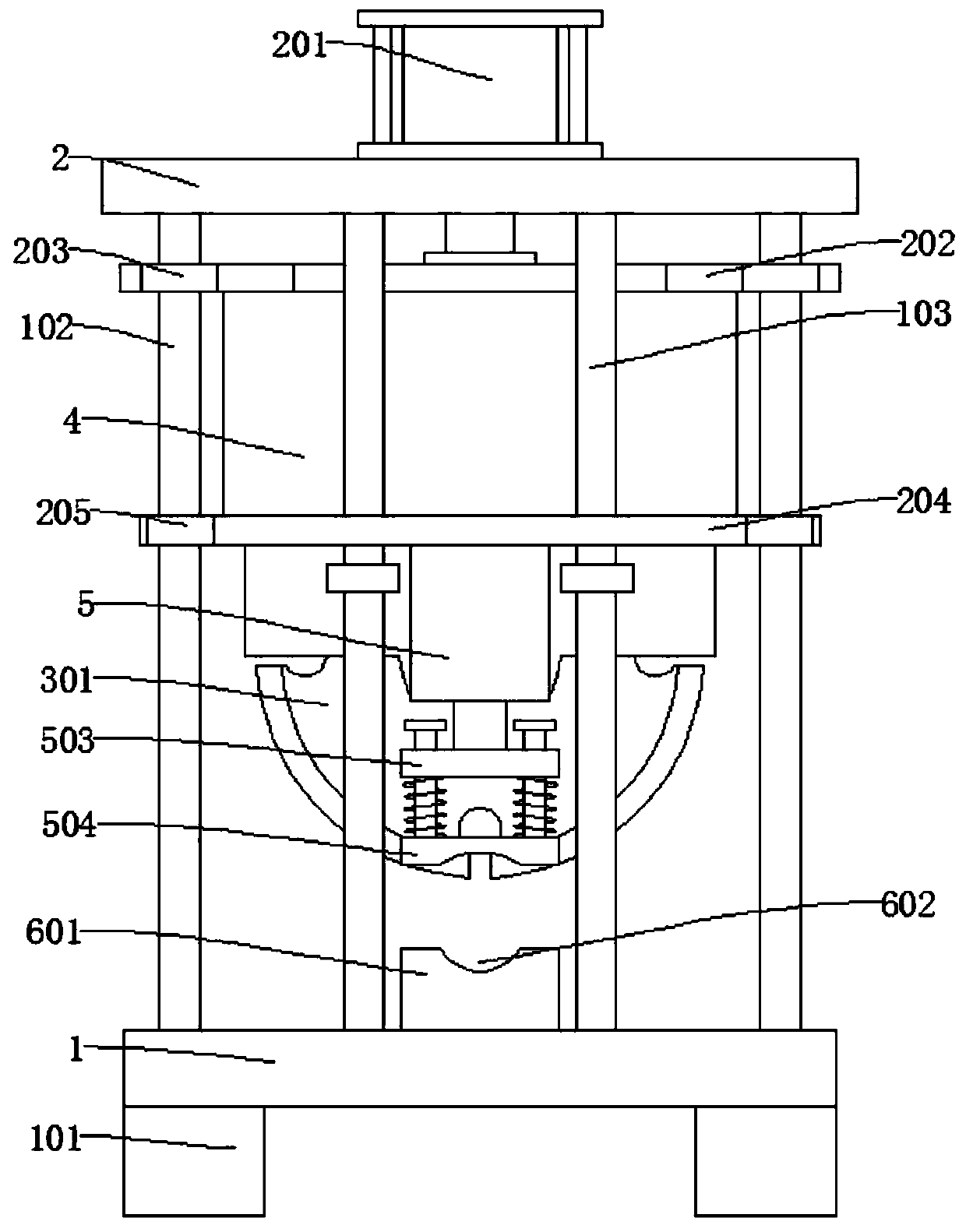
[0036] refer to Figure 1-8 , a wire rope cutting device, comprising a base plate 1 and a top plate 2, a first guide support rod 102 and a second guide support rod 103 are respectively connected between the base plate 1 and the top plate 2;

[0037] The first guide support rod 102 and the second guide support rod 103 are slidably connected with a first horizontal plate 202 and a second horizontal plate 204, the second horizontal plate 204 is fixedly connected with a fixed frame 3, and the fixed frame 3 is rotatably connected with a cutting frame. Sheet 301;

[0038] The bottom of the second horizontal plate 204 is also connected with the cylinder 5, the second connecting rod 501 is slidably connected in the cylinder 5, and the bottom of the second connecting rod 501 is connected with a pressing member;

[0039] The inner wall of the fixed frame 3 is also provided with a nozzle 309 placed obliquely, and the cylinder 5 communicates with the nozzle 309 through a connecting pipe ...

Embodiment 2

[0052] refer to Figure 1-8 , a wire rope cutting device, comprising a base plate 1 and a top plate 2, a first guide support rod 102 and a second guide support rod 103 are respectively connected between the base plate 1 and the top plate 2;

[0053] The first guide support rod 102 and the second guide support rod 103 are slidably connected with a first horizontal plate 202 and a second horizontal plate 204, the second horizontal plate 204 is fixedly connected with a fixed frame 3, and the fixed frame 3 is rotatably connected with a cutting frame. Sheet 301;

[0054] The bottom of the second horizontal plate 204 is also connected with the cylinder 5, the second connecting rod 501 is slidably connected in the cylinder 5, and the bottom of the second connecting rod 501 is connected with a pressing member;

[0055] The inner wall of the fixed frame 3 is also provided with a nozzle 309 placed obliquely, and the cylinder 5 communicates with the nozzle 309 through a connecting pipe ...


PUM


Abstract

The invention discloses a steel wire rope cutting device, and belongs to the field of steel wire rope cutting. The steel wire rope cutting device comprises a bottom plate and a top plate, wherein a first guide supporting rod and a second guide supporting rod are connected between the bottom plate and the top plate separately; the first guide supporting rod and the second guide supporting rod are in sliding connection with a first transverse plate and a second transverse plate, the second transverse plate is fixedly connected with a fixed frame, and the fixed frame is internally and rotatably connected with a cutting piece; the bottom of the second transverse plate is further connected with cylinders, and the bottom of each second connecting rod is connected with a compression part; and theinner wall of the fixed frame is further provided with obliquely-placed spray heads, and the cylinders communicate with the spray heads through connecting pipes. When the steel wire rope cutting device is used for cutting a steel wire rope, the steel wire rope can be prevented from sliding, the cutting cross section is smoother, the selling profits of the steel wire rope are increased, meanwhilethe cutting piece can be cooled to a certain extent, high temperature caused by long-time use is avoided, and the occurrence of safety accidents is avoided.

Description

technical field [0001] The invention relates to the technical field of steel wire rope cutting, in particular to a steel wire rope cutting device. Background technique [0002] The steel wire rope is a spiral steel wire bundle twisted together with steel wires whose mechanical properties and geometric dimensions meet the requirements according to certain rules. The steel wire rope is composed of steel wire, rope core and lubricating grease. The steel wire rope is first twisted into strands by multi-layer steel wires, and then twisted into a helical rope by a certain number of strands with the rope core as the center. In material handling machinery, it is used for lifting, pulling, tensioning and carrying. The steel wire rope has high strength, light weight, stable operation, and is not easy to break suddenly, and the operation is reliable. [0003] During the cutting process of the existing steel wire rope, the steel wire rope will slide, causing the cutting section of the...

Claims


Application Information

Patent Timeline
IPC IPC(8): B21F11/00
CPCB21F11/00
Inventor 李丰王彩云
Owner 唐山天天安科技有限公司
Why Eureka
Try Eureka