Financial binding machine

A binding machine and financial technology, applied in binding, metal processing, etc., can solve the problem of a large handle, and achieve the effect of uniform punching force, convenient operation, and reduced force

Pending Publication Date: 2020-08-28
ZHEJIANG ZHIYUAN OFFICE EQUIP MFG
View PDF1 Cites 1 Cited by
  • Summary
  • Abstract
  • Description
  • Claims
  • Application Information

AI Technical Summary

Problems solved by technology

However, it still has certain defects when it is used. When using the binding machine provided by this prior art to punch holes, the user needs to apply greater strength to the handle, especially for some bindings with hard paper materials or thickness. For thicker bindings, or bindings with different materials that require mixed binding

Method used


Image

  • Financial binding machine
  • Financial binding machine
  • Financial binding machine

Examples


Embodiment example 1

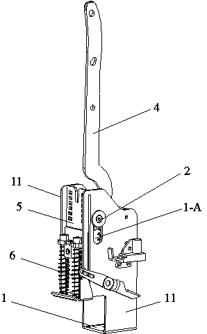
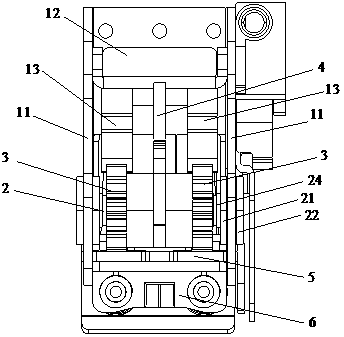
[0026] refer to Figure 1-Figure 3 , financial bookbinding machine, it comprises frame 1, and two side parts 11 of described frame 1 are respectively provided with a linear installation groove 1-A, and both are left and right symmetrical about described frame 1, and described installation groove 1-A is arranged vertically, and its upper and lower ends are in the shape of semi-circular arcs. The frame 1 is provided with a horizontal rotating shaft 2, and the two ends of the rotating shaft 2 respectively pass through the two installation slots 1-A.

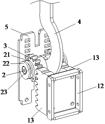
[0027] The two ends of the rotating shaft 2 are sleeved and fixed with guides respectively, and the guides include a first part 21, a second part 22, and a third part 23. The third part 23 is an annular structure, and its position is set The part of the rotating shaft 2 located in the installation groove 1-A, and the second part 22 is slidingly fitted with the two vertical side walls of the installation groove 1-A, the first part 21...


PUM


Abstract

The invention discloses a financial binding machine which comprises a rack. The rack is provided with a rotating shaft. The rotating shaft is sleeved with gears and a handle. The rack is provided witha sliding plate in a sliding manner, wherein the sliding plate can vertically ascend and descend and is engaged with the gears. A perforating portion is fixed to the bottom of the sliding plate. Vertical gear racks are fixed to the two sides of the rack and engaged with the gears. The rack is provided with two mounting grooves in vertical straight line shapes. The two ends of the rotating shaft are arranged in the two mounting grooves and are in sliding fit with the two mounting grooves. The financial binding machine has the beneficial effect that compared with the prior art, more labor is saved during use.

Description

technical field [0001] The invention relates to a financial binding machine, in particular to a relatively labor-saving financial binding machine. Background technique [0002] The prior art publication number CN104875520B discloses a punching device for a bookbinding machine, which includes a punching bracket, a vertical slide plate arranged on the punching bracket, a punching part fixed on the vertical slide plate, A rotary drive mechanism and a pipe cutting mechanism for driving the vertical slide plate up and down on the punching bracket, the pipe cutting mechanism includes a pipe cutting mounting seat, a pipe passing hole arranged on the pipe cutting mounting seat, The cutter provided on the pipe cutting installation seat, the pipe receiving plate located below the cutter, and the cutter push-pull mechanism linked with the rotary drive mechanism to drive the cutter to cut pipes. Certainly, this prior art has simple in structure, is easy to implement; Utilizes elastic b...

Claims


Application Information

Patent Timeline
Patent Type & Authority Applications(China)
IPC IPC(8): B26D5/08B26D5/10B26F1/16B42B5/02B42B5/00
CPCB26D5/083B26D5/10B26F1/16B42B5/00B42B5/02
Inventor 阮永华谭显斌沈锋刚
Owner ZHEJIANG ZHIYUAN OFFICE EQUIP MFG
Why Eureka
Try Eureka