Spiral conveying device

A technology of conveying device and auger, which is applied in the direction of packaging, etc., can solve the problems of inconvenient use, storage and movement, long overall length of auger pump, and increased return resistance, so as to save driving source, improve material return and reduce overall cost Effect

Active Publication Date: 2020-08-28
SHENZHEN MPD HITECH CO LTD
View PDF10 Cites 3 Cited by
  • Summary
  • Abstract
  • Description
  • Claims
  • Application Information

AI Technical Summary

Problems solved by technology

[0004] However, in actual use, it is inevitable to encounter the need to transport materials with slightly better fluidity. During the transportation of materials with slightly better fluidity, there will be material backflow, so that the pumping pressure is not enough, and lengthening the length of the auger can increase the backflow resistance. Increase, so that the pumping pressure increases, but the increase of the auger will lead to a longer overall length of the auger pump, which is inconvenient to use, store and move, and needs further improvement

Method used


Image

  • Spiral conveying device
  • Spiral conveying device
  • Spiral conveying device

Examples


Embodiment 1

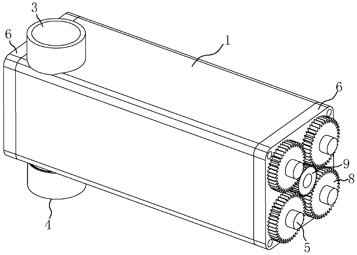
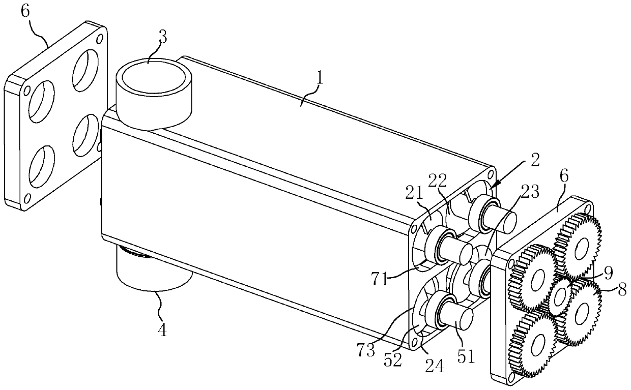
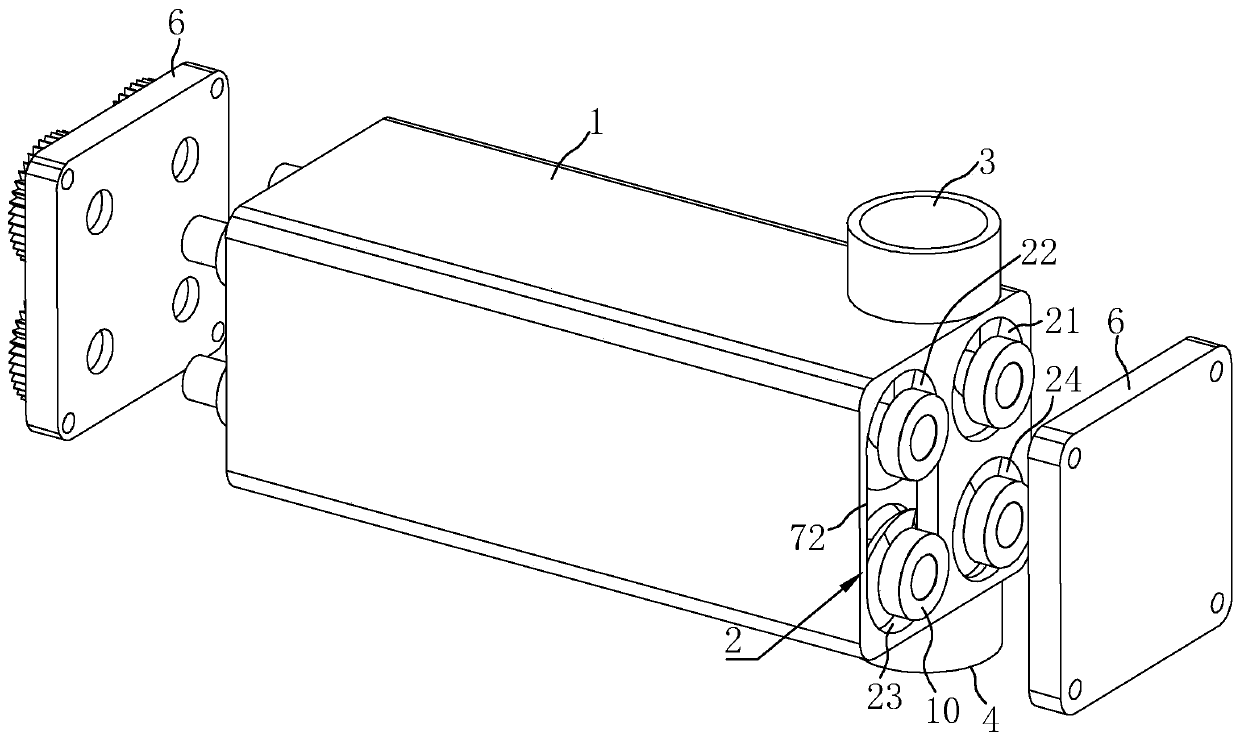
[0037] Embodiment 1: refer to figure 1 and figure 2 , is an auger conveying device disclosed in the present invention, comprising a square-shaped body 1, in which a plurality of conveying cavities 2 are arranged, and in this embodiment, four conveying cavities 2 are set and communicated in sequence, conveying Cavities 2 are arranged in parallel to form a first chamber 21, a second chamber 22, a third chamber 23 and a fourth chamber 24, the first chamber 21 and the second chamber 22 are located above, and the third chamber 23 and the fourth chamber 24 are located below, and each chamber is elongated and has a circular cross section. An inlet 3 communicating with the first chamber 21 is provided on the top side of the body 1, and at the bottom of the body 1 a The side is provided with an outlet 4 communicating with the fourth chamber 24; in the conveying chamber 2, there are screw conveying rods 5 connected in rotation, and the material enters the first chamber 21 from the inl...

Embodiment 2

[0042] Embodiment 2: refer to Figure 4 , is an auger conveying device disclosed in the present invention. The main difference between it and Embodiment 1 is that the outlet 4 includes a plurality of openings 11 arranged on the body 1, wherein there are four openings 11 and are respectively connected with each conveying Corresponding to the cavity 2, the opening 11 is opened at the end of each delivery cavity 2, and at the same time, a sealing plate 12 is horizontally slidably connected to the corresponding opening 11 of the body 1. The sealing plate 12 is used to close the opening 11, and is connected on the sealing plate 12. There is a partition 13 for separating and blocking the communication cavity. The partition 13 and the sealing plate 12 are fixed and move synchronously. The partition 13 is located at the entity between the body 1 corresponding to the adjacent delivery chamber 2, and between the sealing plate 12 and the opening 11 When it is in a staggered state, that i...


PUM


Abstract

The invention relates to a spiral conveying device. The spiral conveying device comprises a machine body, conveying cavities are formed in the machine body, an inlet and an outlet are formed in the machine body, the number of the conveying cavities is at least two, the conveying cavities communicate with one another, a spiral conveying rod is rotationally arranged in each conveying cavity, and theconveying directions of the adjacent conveying cavities are different. According to the spiral conveying device, the conveying cavities which communicate with one another and have different flow directions are arranged, so that the total length of materials flowing through the conveying cavities can be effectively increased, then the materials continuously pass through each conveying cavity to achieve the purpose of pressurization, and the phenomenon of material backflow in the conveying process is effectively improved; and due to the fact that the conveying directions of the adjacent conveying cavities are different and bent positions are formed at communicating positions, a promoting effect can be achieved for preventing materials from flowing back, and due to the fact that the conveying cavities are not overall linear, so that the overall structure is more compact, and storage, movement and use are convenient.

Description

technical field [0001] The invention relates to the technical field of feeding and conveying equipment, in particular to an auger conveying device. Background technique [0002] With the continuous development of society, all walks of life adopt unique conveying methods for feeding materials in the production process. The auger pump is one of the common conveying methods, which mainly drives the screw conveying rod located in the conveying pipe to rotate through the rotation of the motor. To realize the conveying of materials from one end to the other. [0003] For example, the Chinese patent with the notification number CN205471254U discloses a screw auger pump, including a long neck shaft bearing, a shaft coupling, a motor flange, an intermediate connecting sleeve, a packing platen, a packing flange, a packing, and a circular cylinder. body, auger, pump bracket, auger bearing, auger bearing housing cover, auger bearing housing, auger bearing housing bracket, side wall inl...

Claims


Application Information

Patent Timeline
Patent Type & Authority Applications(China)
IPC IPC(8): B65G33/24B65G33/34B65G33/18
CPCB65G33/18B65G33/24B65G33/34
Inventor 王淼黄建生蓝云燕何承平吴峰
Owner SHENZHEN MPD HITECH CO LTD
Why Eureka
Try Eureka