Boom frame system and operation vehicle

A boom and component technology, which is used in hoisting devices, fire rescue, building construction, etc., can solve the problems affecting the stability of the boom system and the working area, and achieve the effects of simple structure, reduced manufacturing difficulty, and easy tilting processing.

Inactive Publication Date: 2020-08-28
SANY AUTOMOBILE MFG CO LTD
View PDF5 Cites 2 Cited by
  • Summary
  • Abstract
  • Description
  • Claims
  • Application Information

AI Technical Summary

Problems solved by technology

[0002] In the existing boom system, the center of gravity of the boom system is often located on the side of the boom system, which makes the boom bear eccentric load and additional torque or side bending moment, seriously affecting the stability and working area of ​​the boom system

Method used


Image

  • Boom frame system and operation vehicle
  • Boom frame system and operation vehicle
  • Boom frame system and operation vehicle

Examples


Embodiment 1

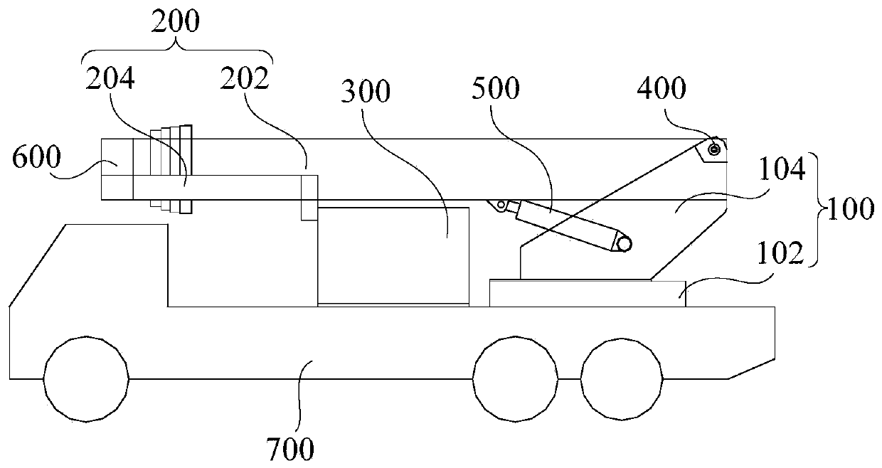
[0047] like figure 1 , figure 2 and image 3 As shown, the first embodiment of the present invention proposes a jib system, including: a turntable 100 and a jib 200 .

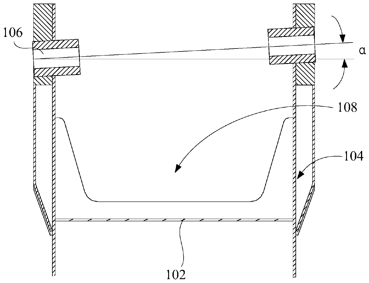
[0048] Wherein, the boom 200 includes a first boom assembly 202 and a second boom assembly 204 , the first boom assembly 202 is hinged to the turntable 100 , and the second boom assembly 204 is located at one side of the first boom assembly 202 . In particular, as image 3 As shown, the hinge axis of the first boom assembly 202 and the turntable 100 forms a preset angle α with the horizontal plane, so that the first boom assembly 202 is inclined on the turntable 100, and the first boom assembly 202 itself will have a certain Pre-twist and pre-deflection. Also, from one side of the first boom assembly 202 to one side of the second boom assembly 204, the axis of articulation slopes upward. That is, the first boom assembly 202 is inclined toward the side away from the second boom assembly 204, so that the pr...

Embodiment 2

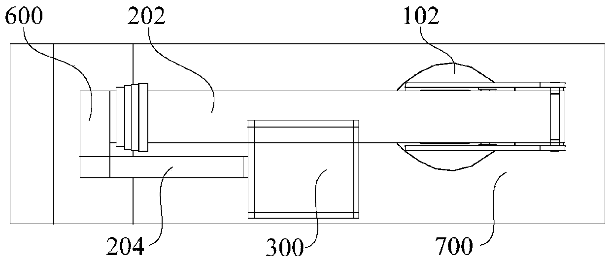
[0053] like figure 1 , figure 2 and image 3 As shown, the second embodiment of the present invention proposes a boom system, including: a turntable 100 and a boom 200 ; the turntable 100 includes a bottom plate 102 and a vertical plate 104 .

[0054] Wherein, the boom 200 includes a first boom assembly 202 and a second boom assembly 204 , the first boom assembly 202 is hinged to the turntable 100 , and the second boom assembly 204 is located at one side of the first boom assembly 202 . In particular, as image 3 As shown, the hinge axis of the first boom assembly 202 and the turntable 100 forms a predetermined included angle α with the horizontal plane, and from one side of the first boom assembly 202 to one side of the second boom assembly 204, the hinge axis is inclined upward , so that the pre-torsion and pre-deflection of the boom 200 itself, and the eccentric load and torque M generated by the installation position of the second boom assembly 204 T or side bending m...

Embodiment 4

[0068] like figure 1 , figure 2 and image 3 As shown, the fourth embodiment of the present invention proposes a boom system, including: a turntable 100 , a boom 200 and an operating platform 300 .

[0069] Wherein, the boom 200 includes a first boom assembly 202 and a second boom assembly 204 , the first boom assembly 202 is hinged to the turntable 100 , and the second boom assembly 204 is located on one side of the first boom assembly 202 . In particular, as image 3As shown, the hinge axis of the first boom assembly 202 and the turntable 100 forms a predetermined included angle α with the horizontal plane, and from one side of the first boom assembly 202 to one side of the second boom assembly 204, the hinge axis is inclined upward , so that the pre-torsion and pre-deflection of the first boom assembly 202 itself, and the eccentric load and torque M generated by the installation position of the second boom assembly 204 T or side bending moment M 0 Balance each other t...


PUM


Abstract

The invention provides a boom frame system and an operation vehicle. The boom frame system comprises a rotary table and boom frames, wherein the boom frames comprise a first boom frame assembly and asecond boom frame assembly, the first boom frame assembly is hinged to the rotary table, and the second boom frame assembly is located on one side of the first boom frame assembly; and a hinge axis ofthe first boom frame assembly and the rotary table form a preset included angle with the horizontal plane, and the hinge axis is inclined upwards from one side of the first boom frame assembly to oneside of the second boom frame assembly. According to the system, only an installation mode of the first boom frame assembly relative to the rotary table is changed, so that the problem of unbalance loading, torque or side bending moment caused by gravity center offset of the boom frame can be solved, great structural improvement is not needed for the boom frame, and excessive other structures need not be added.

Description

technical field [0001] The invention relates to the technical field of engineering machinery, in particular to a boom system and a working vehicle. Background technique [0002] In the existing boom system, the center of gravity of the boom system is often located on the side of the boom system, so that the boom bears eccentric load and additional torque or side bending moment, seriously affecting the stability and working area of ​​the boom system. Contents of the invention [0003] The present invention aims to solve at least one of the technical problems existing in the prior art. [0004] To this end, the first aspect of the present invention provides a boom system. [0005] A second aspect of the present invention provides a work vehicle. [0006] The first aspect of the present invention provides a boom system, including: a turntable; a boom, including a first boom assembly and a second boom assembly, the first boom assembly is hinged to the turntable, and the seco...

Claims


Application Information

Patent Timeline
Patent Type & Authority Applications(China)
IPC IPC(8): B66C23/68B66C23/687B66C23/66B66C23/84B66C23/82F16C11/04B66F11/04E04G21/04A62C27/00
CPCA62C27/00B66C23/66B66C23/68B66C23/701B66C23/826B66C23/84B66F11/04B66F11/044E04G21/04F16C11/04
Inventor 蔡毅姚占磊王仲杰
Owner SANY AUTOMOBILE MFG CO LTD
Why Eureka
Try Eureka