
Warping machine capable of preventing warp damage

A warping machine and warp yarn technology, which is applied in the textile field, can solve problems such as equipment misjudgment, yarn entanglement, and static electricity accumulation, and achieve the effects of preventing warp yarn and equipment damage, facilitating tension maintenance, and realizing adjustment and control

Active Publication Date: 2020-08-28
盛谷(苏州)环保材料有限公司
View PDF8 Cites 1 Cited by
  • Summary
  • Abstract
  • Description
  • Claims
  • Application Information

AI Technical Summary

Problems solved by technology

However, this method also has certain defects. Since the warp yarns on different bobbins have a certain length at the joint, after the last unwinding of the previous bobbin is completed, the tension will suddenly decrease, which will easily cause the equipment to misjudge as A disconnection occurs and a shutdown occurs
At the same time, the sudden and large change of the tension will easily cause the yarn to be entangled, which will cause damage to both the yarn and the equipment.
In addition, because the range of tension reduction is too large, even if the warping machine is equipped with a device for real-time tension detection and online correction, it is often impossible to quickly correct tension imbalance
[0005] 2. During the process from unwinding to winding, the warp yarn passes through the wires of several guide parts, such as: guide wheels, guide rods, guide holes, etc. In the process of warp yarn contacting these guide parts, there will inevitably be some frictional force, which in turn leads to the accumulation of static electricity on the surface of the warp yarn. The accumulation of static electricity will not only affect the quality of the warp yarn itself, but also cause certain safety hazards
This results in a relatively scattered distribution of creels in the width direction, which in turn causes warp yarns to have a large bending angle when passing through the yarn collecting plate. If the bending angle is too large, it will not only wear the warp yarns, but also increase the number of broken threads. risks of

Method used

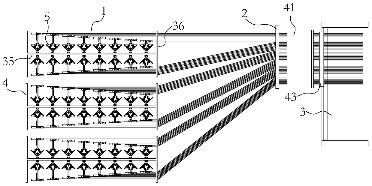
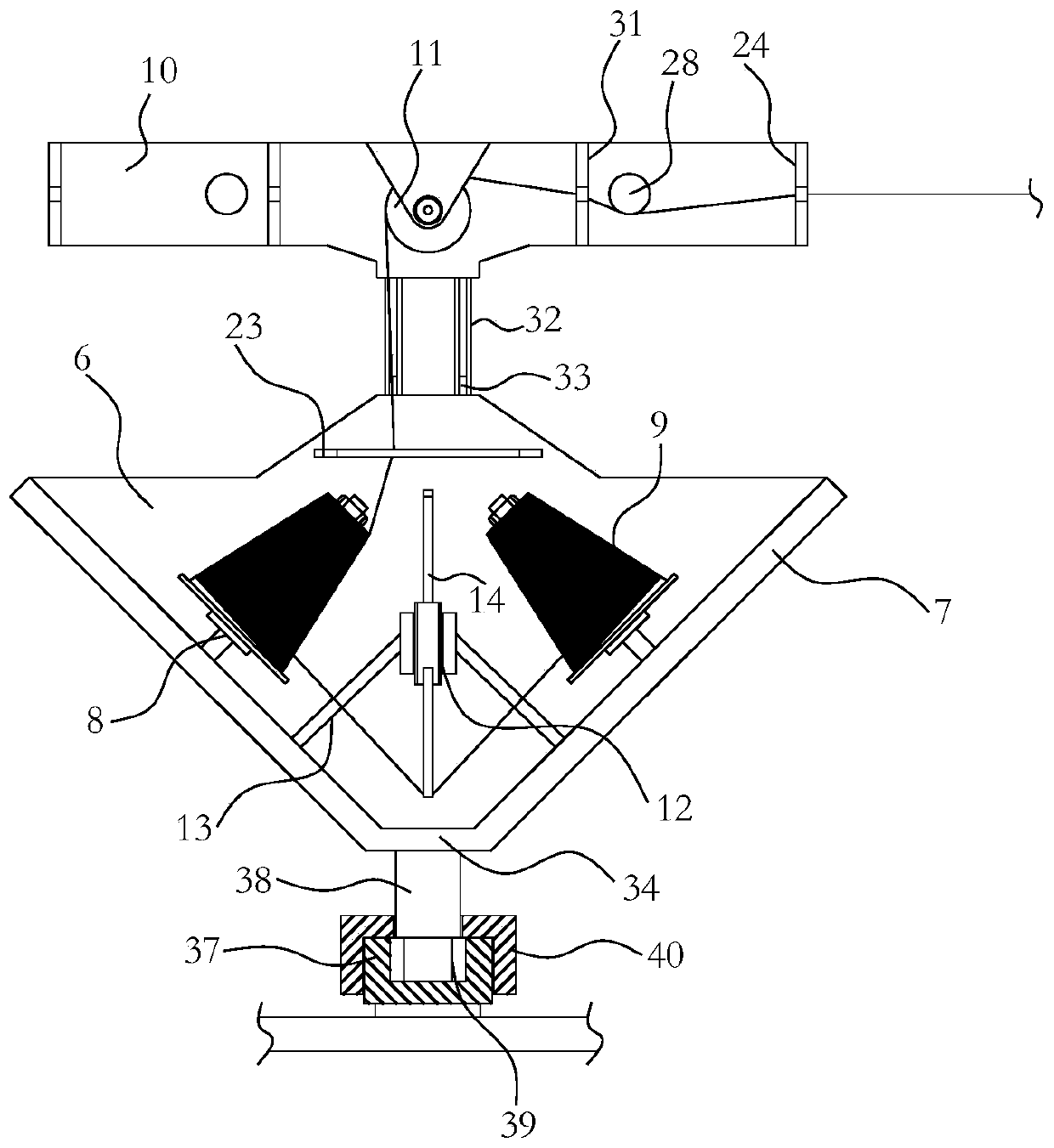

Image

  • Warping machine capable of preventing warp damage
  • Warping machine capable of preventing warp damage
  • Warping machine capable of preventing warp damage

Examples


Embodiment Construction

[0036] Such as Figure 1-15A warping machine shown to prevent warp damage is the same as a traditional warping machine in that the present invention also includes a creel 1 , a yarn collecting plate 2 and a warping machine main body 3 arranged in sequence. The creel 1 is used to install the yarn bobbin and is used for unwinding the bobbin; the yarn collecting plate 2 is used to guide the warp yarn unwound from the creel 1 so that it can enter the main body of the warping machine 3 normally The swimming device 43 can move along the length direction of the warp shaft of the warping machine main body 3, so that the warp yarns can be wound on the warp shaft in an orderly manner.

[0037] In combination with the various problems mentioned in the background technology, the present invention improves the existing warping machine in many aspects, so as to improve the overall working performance of the warping machine:

[0038] First, from the improvement of the creel structure:

[0...


PUM


Abstract

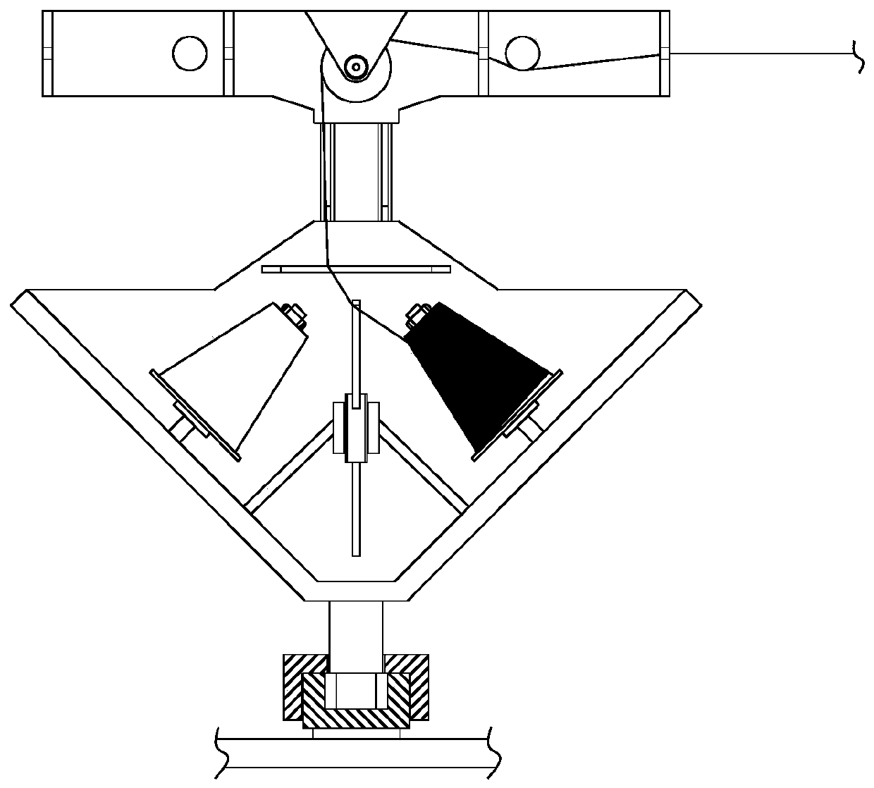
The invention relates to the technical field of textiles, and aims to provide a warping machine capable of balancing unwinding tension and preventing warp damage. The warping machine comprises a bobbin creel, and the bobbin creel comprises a creel body and a plurality of unwinding units arranged on the creel body; each unwinding unit comprises a mounting frame, each mounting frame comprises a transverse bottom plate and two vertical side plates, each bottom plate is in a right triangle shape, and the side plates are fixedly arranged on the two right-angle sides of the corresponding bottom plate; two bobbin mounting bases capable of freely rotating are symmetrically arranged on the two side plates, yarn bobbins are arranged on the bobbin mounting bases in a sleeving mode, and the yarn bobbins are distributed in an inverted V shape; and a damping type tension abrupt drop buffer is arranged in the area, located between the two yarn bobbins, of each mounting plate. According to the warpingmachine, the yarn bobbins can be replaced without shutdown, meanwhile, the situation that when one yarn bobbin is unwound and switched to the other bobbin for unwinding, the tension is reduced too much due to the influence of the length of a splicing section can be reduced, tension adjustment and control are effectively achieved, and warp and equipment damage is prevented.

Description

technical field [0001] The invention relates to the technical field of textiles, in particular to a warping machine for preventing warp damage. Background technique [0002] The warping machine is a device that winds a certain number of warp yarns on the warp beam according to a certain width and evenly spaced according to the process design requirements. It mainly includes a creel, a yarn collecting board and the main body of the warping machine. Guided by the mechanism, it is evenly wound on various parts of the warp beam in turn. In the long-term practice process, the inventor has found that the existing warping machines mainly have the following problems: [0003] 1. The traditional warping creel includes a single creel and a double creel. A yarn bobbin can be set in each unwinding unit of a single creel. When the unwinding speed and conveying speed of the bobbin are good, since the warp yarns on multiple bobbins can basically be unwound synchronously, it is also poss...

Claims


Application Information

Patent Timeline
Patent Type & Authority Applications(China)
IPC IPC(8): D02H3/00D02H1/00D02H13/26D02H13/00
CPCD02H1/00D02H3/00D02H13/00D02H13/26
Inventor 宋良亮
Owner 盛谷(苏州)环保材料有限公司
Learn More