Fixing device for underground pipe gallery installation and using method for fixing device

A technology for fixing devices and underground pipe galleries, applied in underwater structures, water conservancy projects, artificial islands, etc., can solve the problems of poor assembly of roof and side plates, affecting the convenience of pipe gallery installation, and uneven pouring of pipe galleries , to achieve the effect of improving the structural strength, enhancing the overall structural strength and reducing the difficulty

Active Publication Date: 2020-08-28
WUHAN YASIDA SCI & TECH CO LTD
View PDF6 Cites 1 Cited by
  • Summary
  • Abstract
  • Description
  • Claims
  • Application Information

AI Technical Summary

Problems solved by technology

[0003] In the process of installing the pipe gallery, it is necessary to install the side plate of the pipe gallery first, then install the top plate between the two side plates, and then splice multiple pipe galleries, and then pour concrete to realize the pipe gallery. During the installation of the pipe gallery, the side plates may tilt due to the height, which will cause the side plates on both sides to tilt towards the middle, resulting in poor assembly between the hoisted top plate and the side plates. The gaps between adjacent pipe galleries will also lead to uneven pouring, and even holes, which will affect the structural strength of the pipe gallery and affect the convenience of installation of the pipe gallery; accordingly, the present invention proposes a Fixing device for installation of underground pipe gallery and method of use thereof

Method used


Image

  • Fixing device for underground pipe gallery installation and using method for fixing device
  • Fixing device for underground pipe gallery installation and using method for fixing device
  • Fixing device for underground pipe gallery installation and using method for fixing device

Examples


Embodiment approach

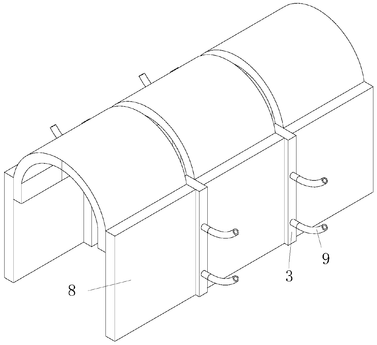
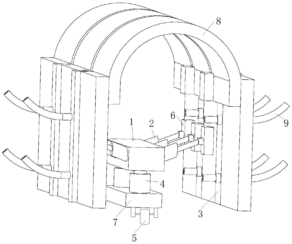
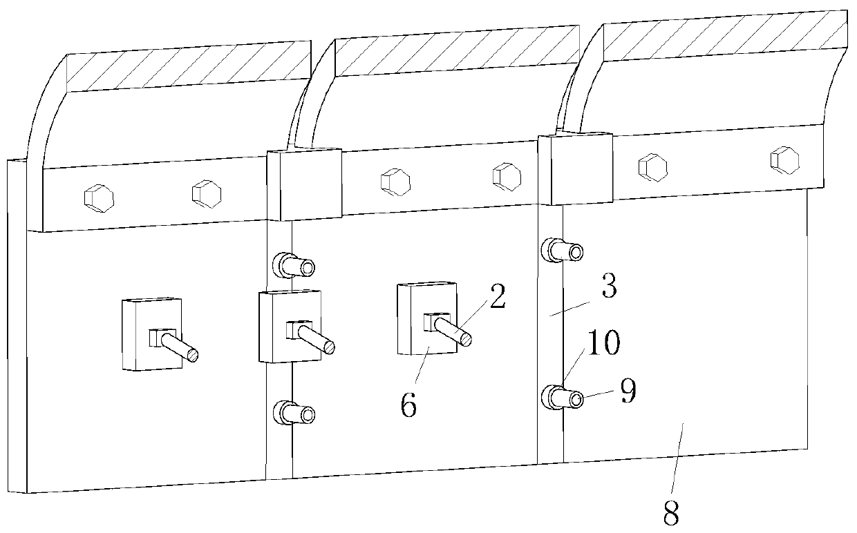
[0030] As an embodiment of the present invention, one side of the insertion rod 9 is arranged in an arc shape, wherein two swing plates 11 are hinged at one end of the arc shape of the insertion rod 9 ; the two swing plates 11 are symmetrically distributed. When working, the other end of the insertion rod 9 is arranged in an arc shape, which can have a better grip on the filling block 3 after being inserted into the soil. At the same time, the swing plate 11 provided at the end of the insertion rod 9 can be inserted into the soil The force swings and opens, thereby further increasing the contact area with the soil, so that the pulling effect of the insertion rod 9 on the filling block 3 is further enhanced.

[0031] As an embodiment of the present invention, the insertion rod 9 is provided with a cylindrical through groove 12; a sliding rod 13 is inserted into the cylindrical through groove 12; Two connecting rods 14 are hinged at one end of the sliding rod 13 close to the swi...


PUM


Abstract

The invention belongs to the technical field of underground pipe gallery installation, and particularly relates to a fixing device for underground pipe gallery installation and a using method of the fixing device. The fixing device comprises a shell, hydraulic rods, filling blocks, an ascending air cylinder and traveling wheels;a group of hydraulic rods are arranged, and the group of hydraulic rods are hinged to the two sides of the shell correspondingly; a fixed plate is hinged to the extending end of each hydraulic rod; a base plate is arranged at the bottom of the shell; the traveling wheels are installed at the bottom of the base plate; the bottom end of the ascending air cylinder is fixedly connected with the upper portion of the base plate, and the telescopic end of the ascending aircylinder is connected with the bottom of the shell; and the filling blocks are installed in gaps between every two adjacent pipe galleries, each filling block is arranged to be of a T-shaped structure, and a sloping grain groove is formed in the side, located in the pipe gallery, of each filling block. According to the fixing device, the filling blocks are forcibly pressed into the gaps between the two pipe galleries, so that the filling blocks are in interference fit connection, the structural strength of the splicing positions of the pipe galleries is greatly improved, and the difficulty ofconcrete pouring is also reduced.

Description

technical field [0001] The invention belongs to the technical field of underground pipe gallery installation, in particular to a fixing device for underground pipe gallery installation and a use method thereof. Background technique [0002] The urban underground pipeline comprehensive corridor is also called "common ditch" and "common pipeline". In the tunnel, there are special inspection openings, hoisting openings and monitoring systems, which implement unified planning, design, construction and maintenance, and are comprehensive, long-term, maintainable, earthquake-resistant and disaster-proof, environmentally friendly, and low-cost. characteristics such as sex. The urban underground pipeline is the lifeline of the city, and the comprehensive pipeline corridor is an important guarantee to ensure the stability and safety of the city's "lifeline" and reduce maintenance costs in the later period. The function of the comprehensive pipe corridor to the city is like the funct...

Claims


Application Information

Patent Timeline
Patent Type & Authority Applications(China)
IPC IPC(8): E02D29/045
CPCE02D29/10
Inventor 文琪彭芸欣王庆远文明珠
Owner WUHAN YASIDA SCI & TECH CO LTD
Why Eureka
Try Eureka