grain dryer

A grain dryer and grain technology, applied in the field of grain dryers and grain drying devices, can solve the problems of limitation, broken grains, time-consuming and labor-intensive, etc., and achieve the effect of improving drying efficiency

Active Publication Date: 2022-04-29
徐州蔬客达农业科技有限公司
View PDF12 Cites 0 Cited by
  • Summary
  • Abstract
  • Description
  • Claims
  • Application Information

AI Technical Summary

Problems solved by technology

[0002] Grain needs to be dried after harvesting. Now the way to dry the grain is to spread the grain on the ground, expose it to the sun for drying, and dry it naturally. Turning the grains manually is time-consuming and labor-intensive. Most of the existing grain drying machines stir the grains inside to heat them evenly. necessary waste
[0003] Notification number CN207066025U discloses a grain drying device that is easy to adjust. The device includes a grain drying bottom plate, a water collecting tank is fixedly connected to the top of the grain drying bottom plate, and a first fixed block is fixedly connected to the inner right wall of the water collecting tank. The top of the first fixed block is fixedly connected with a fixed plate, and the end of the fixed plate away from the first fixed block is hinged with a grain drying plate, and the upper surface of the grain drying plate is provided with a water leakage hole, and the device does not have a structure to stir the grain , cannot guarantee the internal dryness of the grain, and depends on the weather for drying, which is limited
[0004] The announcement number CN104126658A discloses a drum-type grain dryer. The grain drying inner cylinder is sleeved inside the grain drying outer cylinder. The inner wall of the grain drying inner cylinder is provided with a grain turning device, and the center of the grain drying inner cylinder is coaxially arranged. There is a central spiral turning device, the inner wall of the grain drying outer cylinder is provided with a heating plate, the lower end of the grain drying inner cylinder is equipped with a first driving motor and a second driving motor, the first driving motor is connected to the central spiral turning device through a pulley, and the second The drive motor is connected to the bottom of the grain drying inner cylinder through the belt wheel. A pair of rotating rollers are arranged on the outer wall of the grain drying outer cylinder. The rotating rollers are welded on the U-shaped dryer bracket. When the device is stirring the grain, the middle The rotation of the turning device makes it easy for the grain to continuously collide with the wall of the cylinder, so that some grains are shelled, and the shelled grains are constantly stirred inside, which in turn causes the grains to break. After the broken grains are mixed with the grain shell, it is inconvenient to separate. cause waste

Method used


Image

  • grain dryer
  • grain dryer
  • grain dryer

Examples


Embodiment 1

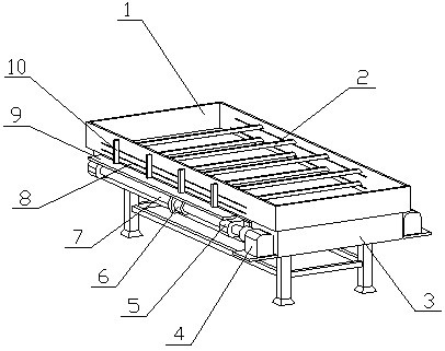
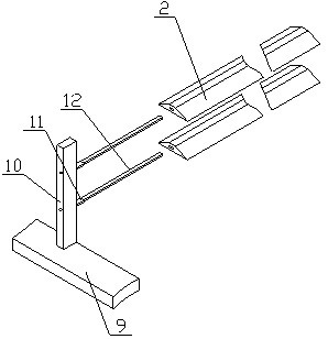
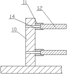
[0020] The grain drying machine of the present invention is realized in this way: the grain drying machine of the present invention consists of a drying box (1), a drying sheet (2), a bracket (3), a stepping motor (4), a mounting seat (5), and a ball screw cover (6), ball screw (7), sliding groove (8), moving plate (9), moving seat (10), moving block (11), heating core (12) and wiring hole (14), the said The drying box (1) is fixedly placed on the top of the support (3), and there are multiple sliding slots (8) on the two opposite sides of the drying box (1), and the sliding grooves (8) on a single side of the drying box (1) The slots (8) are arranged longitudinally, the positions of the sliding slots (8) on the two sides of the drying box (1) are staggered, and the two stepping motors (4) are respectively fixed on both sides of the bracket (3) close to one end One end of the two ball screws (7) and the motor shafts of the two stepping motors (4) are connected in one-to-one co...

Embodiment 2

[0026] The difference between this embodiment and Embodiment 1 is: there are triangular grooves (13) on both sides of the drying sheet (2); when in use, the contact area between the drying sheet (2) and the grain can be increased to improve the drying efficiency;

[0027] The design that the thickness of the drying sheet (2) gradually decreases from the middle to both sides can facilitate the movement of the drying sheet (2) to both sides, reduce the resistance when moving, and increase the contact area with the grain inside the drying box (1) at the same time , improve the drying effect;

[0028] The mobile seat (10) on both sides of the drying box (1) is designed with a plurality of wiring grooves, after the wiring on both sides of the drying box (1) can be connected uniformly, all the heating cores (12 ) for power-on work, to avoid too many external wires affecting the normal use of the device;

[0029] The bottom side of the drying box (1) is designed with a grain outlet ...


PUM


Abstract

The grain drying machine of the present invention discloses a grain drying machine that heats and dries the grain inside the drying box by moving multi-layer drying sheets in different directions, and can avoid damaging the grain particles, and is characterized in that the drying box is fixedly placed on the top of the bracket , there are a plurality of sliding grooves on the two opposite sides of the drying box, the sliding grooves on a single side of the drying box are arranged longitudinally, the positions of the sliding grooves on the two sides of the drying box are staggered, and the two sides The stepping motors are respectively fixed on both sides of the bracket close to one end, and one end of the two ball screws is connected to the motor shafts of the two stepping motors in a one-to-one correspondence, and the two ends of the ball screws are respectively equipped with The mounting seat, the mounting seat is connected with the bracket, the outer surface of the part of the ball screw located in the mounting seat is a smooth surface, the ball screw can rotate in the mounting seat, and the ball screw sleeve is screwed on the ball screw.

Description

technical field [0001] The grain drying machine of the invention relates to a device used for grain drying and belongs to the field of agricultural equipment. In particular, it relates to a grain dryer which heats and dries the grain inside the drying box by moving multi-layer drying sheets in different directions, so as to avoid damage to grain particles. Background technique [0002] Grain needs to be dried after harvesting. Now the way to dry the grain is to spread the grain on the ground, expose it to the sun for drying, and dry it naturally. Turning the grains manually is time-consuming and labor-intensive. Most of the existing grain drying machines stir the grains inside to heat them evenly. Necessary waste. [0003] Notification number CN207066025U discloses a grain drying device that is easy to adjust. The device includes a grain drying bottom plate, a water collecting tank is fixedly connected to the top of the grain drying bottom plate, and a first fixed block is...

Claims


Application Information

Patent Timeline
Patent Type & Authority Patents(China)
IPC IPC(8): F26B11/22F26B23/06F26B25/04F26B25/18A23B9/08
CPCF26B11/22F26B23/06F26B25/04F26B25/18A23B9/08F26B2200/06
Inventor 不公告发明人
Owner 徐州蔬客达农业科技有限公司
Why Eureka
Try Eureka