MMC converter valve submodule online monitoring method and system

A sub-module and converter valve technology, applied in the electrical field, can solve the problems of inaccurate and intuitive health assessment of the MMC converter valve sub-module, and achieve the effect of improving reliability

Active Publication Date: 2020-08-28
GLOBAL ENERGY INTERCONNECTION RES INST CO LTD +2
View PDF14 Cites 7 Cited by
  • Summary
  • Abstract
  • Description
  • Claims
  • Application Information

AI Technical Summary

Problems solved by technology

[0003] Therefore, the technical problem to be solved by the present invention is to overcome the conventional quantity of the operating state of the MMC converter valve sub-module in the prior art, thus

Method used


Image

  • MMC converter valve submodule online monitoring method and system
  • MMC converter valve submodule online monitoring method and system
  • MMC converter valve submodule online monitoring method and system

Examples


Embodiment 1

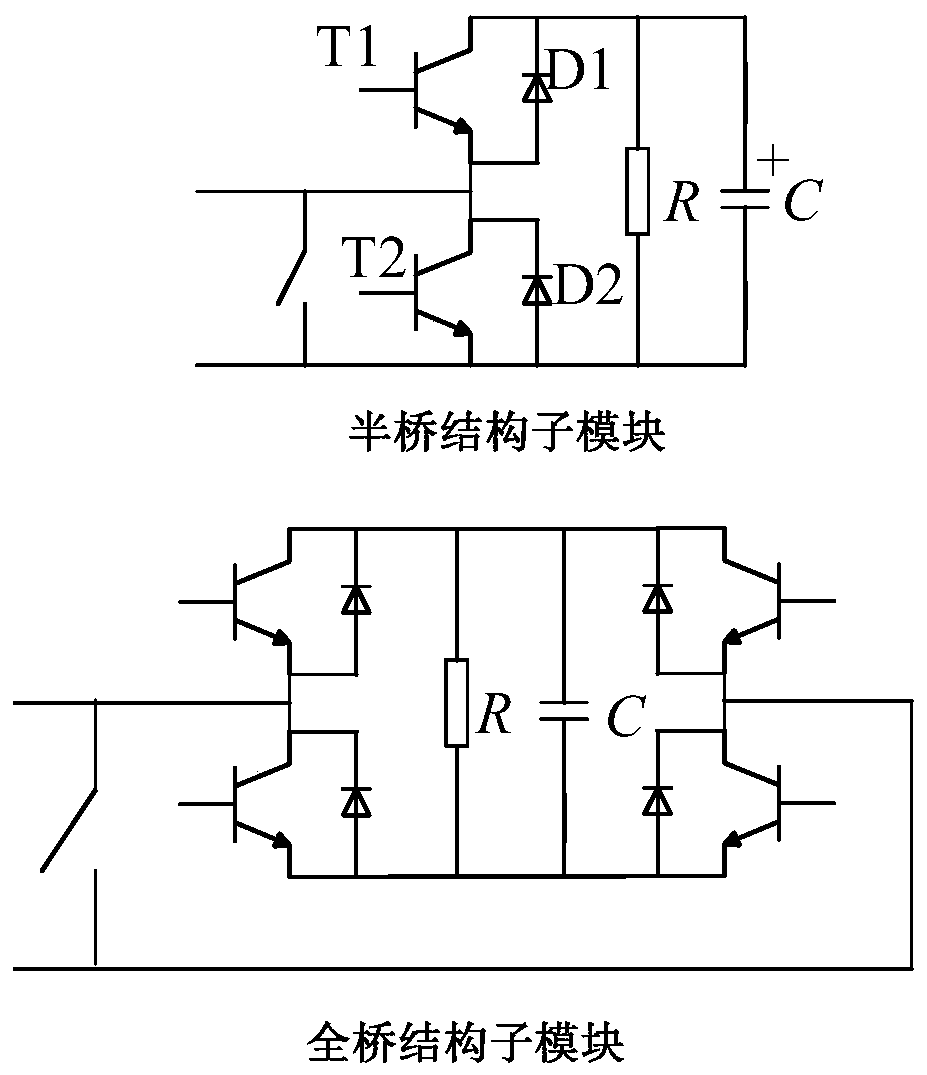
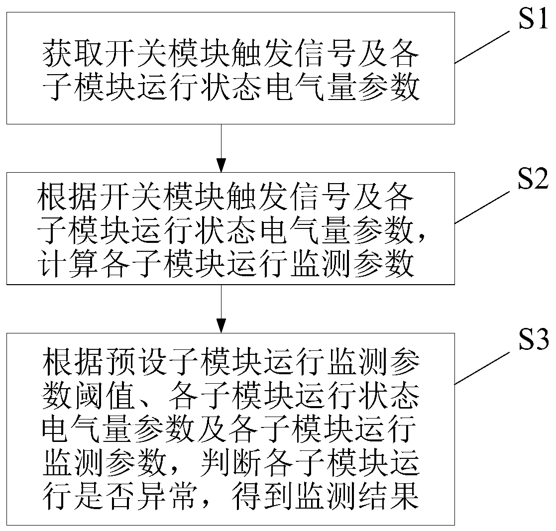
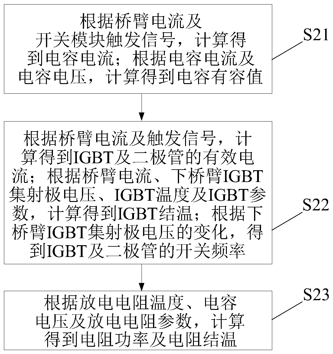
[0030] An embodiment of the present invention provides an online monitoring method for an MMC converter valve sub-module, which is applied to occasions where various components in a large-scale MMC converter valve sub-module need to be monitored. The MMC converter valve sub-module includes a plurality of switch modules, Discharge resistors and capacitors, multiple switch modules form a bridge circuit structure, discharge resistors and capacitors are connected in parallel with the bridge circuit, MMC converter valve sub-modules such as figure 1 as shown, figure 1 The switch module in the structure constitutes a half-bridge structure or a full-bridge structure. The switch module is composed of an IGBT connected in antiparallel with a diode. In addition, multiple switch modules can simultaneously form a three-phase converter valve, a half-wave converter, etc., and the switch module can be composed of Other components, such as MOSFET, GTO, etc. like figure 2 As shown, online mo...

Embodiment 2

[0075] An embodiment of the present invention provides an online monitoring system for an MMC converter valve sub-module, which is used to implement the online monitoring method for an MMC converter valve sub-module described in Embodiment 1. MMC converter valve sub-module such as figure 1 As shown, the control device of the MMC converter valve includes a sub-module controller and a valve base controller, each sub-module corresponds to a sub-module controller, figure 1 The switching module in is composed of an IGBT antiparallel with a diode, but the switching module can also be composed of other switching components. like Figure 5 As shown, the online monitoring system includes: a parameter collection module 1 , a data collection module 2 and a data processing module 3 .

[0076] The parameter collection module is used to obtain the trigger signal of the switch module and the electrical quantity parameters of the operating status of each sub-module.

[0077] In the embodim...


PUM


Abstract

The invention discloses an MMC converter valve submodule on-line monitoring method and system. The method comprises the steps of: obtaining a switch module trigger signal and operation state electrical quantity parameters of all submodules; calculating operation monitoring parameters of each sub-module according to the switch module trigger signal and the operation state electrical quantity parameters of each sub-module; and according to a preset sub-module operation monitoring parameter threshold, the operation state electrical quantity parameters of each sub-module and the operation monitoring parameters of each sub-module, judging whether the operation of each sub-module is abnormal or not, and obtaining a monitoring result. According to the invention, the measured electrical quantity parameters of the operation states of the sub-modules are analyzed and calculated; and the multi-submodule operation monitoring parameters capable of visually reflecting the operation state of the converter valve submodule are obtained, so that maintenance personnel can conveniently monitor the MMC converter valve submodule at multiple angles, and the safe operation of the converter valve can be more accurately, more conveniently and more effectively maintained.

Description

technical field [0001] The invention relates to the field of electrical technology, in particular to an on-line monitoring method and system for an MMC converter valve sub-module. Background technique [0002] With the rapid development and application of Modular Multilevel Converter (MMC) in DC transmission fields such as power grid transmission and offshore wind power connection, the operational reliability and safety of converter valves are particularly important. As the core equipment of flexible DC transmission, the converter valve will always be subjected to impacts from inside and outside the system and aging tests. In the lightest cases, the sub-module bypasses and exits, and in severe cases, the system trips due to a converter valve failure. The existing monitoring of the MMC converter valve is only through the detection of the frequency of the trigger signal issued by the valve base controller and the feedback signal of the IGBT switch state, but only some monitori...

Claims


Application Information

Patent Timeline
IPC IPC(8): G01R31/00
CPCG01R31/00Y02E60/60
Inventor 冯静波邓卫华胡榕孙雯王方方党青洪梓洋
Owner GLOBAL ENERGY INTERCONNECTION RES INST CO LTD
Why Eureka
Try Eureka