
Temperature compensation type plastic optical system and manufacturing method thereof

An optical system and temperature compensation technology, which is applied in optics, optical components, installation, etc., can solve problems such as poor imaging effect and agglomeration changes, and achieve the effect of light weight, light system weight, and easy mass production

Inactive Publication Date: 2020-08-28
QINGDAO LASENCE
View PDF12 Cites 0 Cited by
  • Summary
  • Abstract
  • Description
  • Claims
  • Application Information

AI Technical Summary

Problems solved by technology

The present invention solves the problem that the plastic lens in the prior art has poor imaging effect due to effective aggregation changes when the temperature rises.

Method used

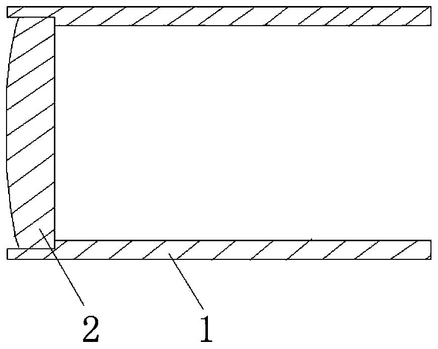

Image

  • Temperature compensation type plastic optical system and manufacturing method thereof
  • Temperature compensation type plastic optical system and manufacturing method thereof
  • Temperature compensation type plastic optical system and manufacturing method thereof

Examples


Embodiment 1

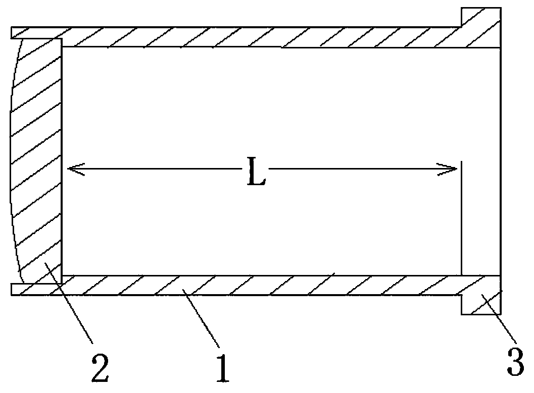
[0046] When the temperature of the molded lens 2 changes, the refractive index of its material will change obviously, which will cause its effective focal length to change with the temperature. At the same time, affected by the temperature, the surface shape of the molded lens 2 will also change, which will also affect the effective focal length of the lens.

[0047] Using professional simulation software, it is possible to simulate and calculate when the temperature changes ΔT, the refractive index change Δn of the molded lens 2, and the effective focal length (EFL) change Δf1 caused by the refractive index change. At the same time, the surface shape change caused by the temperature change ΔT causes the change of the effective focal length (EFL) to be Δf2.

[0048] like figure 2 As shown, the plastic lens 2 and the plastic compensating shell 1 are bonded together, and the plastic compensating shell 1 is connected with a connection part 3, through which the connection part 3...

Embodiment 2

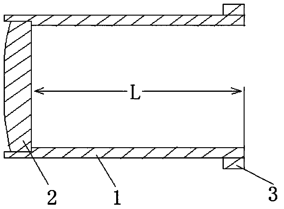
[0051] like image 3 As shown, the difference between the present embodiment and the first embodiment is that the connection part 3 is connected outside the plastic compensating housing 1 .

Embodiment 3

[0053] like Figure 4As shown, two groups of optical systems are provided, and multiple groups of optical systems can also be provided, which can be selected according to actual needs. In the figure, viewed from the right incident end to the left, there are plastic compensating housing 1 and plastic compensating housing 1 in turn. Plastic compensating housing 1 is provided with plastic lens 2 and plastic compensating housing 1 The plastic lens 2 is set in the second; the free expansion length of the plastic compensation housing 1 is L1, and the linear expansion coefficient of the plastic compensation housing 1 is at1; the length of the plastic compensation housing 1 is L2, and the plastic compensation housing 1 is L2. The coefficient of linear expansion of the compensation housing 1 is at2. It is guaranteed that the molded lens 2 one (Δf1+Δf2)+the molded lens 2 two (Δf1+Δf2)=ΔT*L*at1+ΔT*L*at2.


PUM


Abstract

The invention relates to the field of optical application of lenses, in particular to a temperature compensation type plastic optical system. The temperature compensation type plastic optical system comprises a plastic compensation shell body and a plastic lens, and the plastic lens is connected in the plastic compensation shell body, so that the plastic compensation shell body and the plastic lens meet the following formula: [delta]f=[delta]T*L*at, wherein [delta]f is the effective focal length change of the plastic lens during temperature change, [delta]T is temperature change, L is the horizontal distance from the incident end, facing the light path, of the plastic lens to the end of the plastic compensation shell, and at is the linear expansion coefficient of the plastic compensation shell. According to the invention, the thermal properties of the plastic lens and the plastic compensation shell are respectively utilized, so that the problem of wide-temperature application of a plastic optical system is solved; and the whole optical system is made of a plastic material, and compared with a glass lens metal shell, the system is light in weight, low in cost, high in material selectivity and capable of being produced in batches through mold pressing.

Description

technical field [0001] The invention relates to the optical application field of lenses, in particular to a temperature-compensated plastic optical system and a manufacturing method thereof. Background technique [0002] The optical system generally consists of a single or multiple optical lenses and a mechanical optical cavity. According to different application scenarios, there are different requirements for temperature, humidity and vibration resistance. The current optical lenses are generally made of glass or plastic materials. Optical lenses made of glass have more stable performance, but the price is higher; optical lenses made of plastic are not very stable in temperature characteristics, but the price is lower. Among them, the refractive index and surface shape of the plastic lens will change when the material changes in temperature, and the optical properties will often change greatly. Contents of the invention [0003] The object of the present invention is to...

Claims


Application Information

Patent Timeline
Patent Type & Authority Applications(China)
IPC IPC(8): G02B7/02
CPCG02B7/028G02B7/021
Inventor 亓玉凯
Owner QINGDAO LASENCE
Learn More