Alveolar ventilation monitoring system based on non-invasive ventilator and control method

A monitoring system and control method technology, which is applied in the direction of respirators, respiratory organs, and medical equipment, can solve the problems of secondary trauma of patients, secondary trauma of lungs, and delay in treatment of patients, so as to reduce trauma and relieve pain , improve the effect of the smooth effect

Inactive Publication Date: 2020-09-01
HUNAN VENTMED MEDICAL TECH CO LTD
View PDF3 Cites 5 Cited by
  • Summary
  • Abstract
  • Description
  • Claims
  • Application Information

AI Technical Summary

Problems solved by technology

When the patient's breathing state is insufficient, it will lead to hypoxia and affect the treatment; when the patient's breathing state is too high, it will cause secondary trauma to the lungs and delay the patient's treatment; secondary trauma

Method used


Image

  • Alveolar ventilation monitoring system based on non-invasive ventilator and control method
  • Alveolar ventilation monitoring system based on non-invasive ventilator and control method
  • Alveolar ventilation monitoring system based on non-invasive ventilator and control method

Examples


Embodiment 1

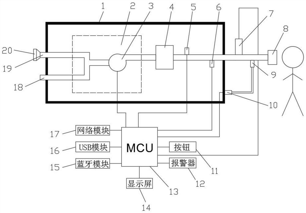
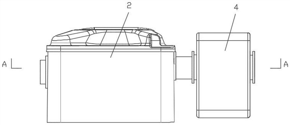
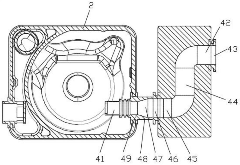
[0038] Such as figure 1 As shown, the specific structure of the present invention is: an alveolar ventilation monitoring system based on a non-invasive ventilator, which includes a ventilator body 1, an MCU 13 and a user breathing terminal 8, wherein the ventilator body 1 is provided with a pneumatic electric adjustment Module 3, the air intake end of the air pressure electric adjustment module 3 is connected to the gas inlet, the output end of the air pressure electric adjustment module 3 is connected to the airflow pressure buffer module 4, and the airflow output end of the airflow pressure buffer module 4 is connected to the user's breathing end 8; the ventilator Inside the body 1 and at the output end of the airflow pressure buffer module 4, a differential pressure flow sensor 5 and a first pressure sensor 6 are provided; the pneumatic electric adjustment module 3, the differential pressure flow sensor 5 and the first pressure sensor 6 are all connected The MCU13 is electr...

Embodiment 2

[0053] In this example, if figure 1 As shown, the specific structure of the present invention is as follows: it includes a ventilator body 1, an MCU 13 and a user breathing end 8, wherein, the interior of the ventilator body 1 is provided with a pneumatic electric adjustment module 3, and the air intake end of the air pressure electric adjustment module 3 is connected to The gas inlet, the output end of the air pressure electric adjustment module 3 is connected to the airflow pressure buffer module 4, and the airflow output end of the airflow pressure buffer module 4 is connected to the user's breathing end 8; The output end is provided with a differential pressure flow sensor 5 and a first pressure sensor 6 ; the pneumatic electric adjustment module 3 , the differential pressure flow sensor 5 and the first pressure sensor 6 are all electrically connected to the MCU 13 .

[0054] In this example, if figure 1 As shown, the differential pressure flow sensor 5 and the first pres...


PUM


Abstract

The invention discloses an alveolar ventilation monitoring system based on a non-invasive ventilator and a control method. The system comprises a breathing machine body, a user breathing end, an MCU and a display screen, wherein an air pressure electric adjusting module is arranged in the breathing machine body, and a differential pressure type flow sensor and a first pressure sensor are arrangedat the output end of the air pressure electric adjusting module; the air pressure electric adjusting module, the differential pressure type flow sensor and the first pressure sensor are all electrically connected with the MCU; and the differential pressure type flow sensor and the first pressure sensor acquire the gas flow and pressure output by the air pressure electric adjusting module respectively, and the MCU acquires detection data of the differential pressure type flow sensor and the first pressure sensor and displays the detection data through the display screen. The breathing state ofa patient can be monitored, the airflow pressure is intelligently compensated and adjusted according to the breathing state of the patient, the patient is helped to keep the optimal breathing state, and a powerful guarantee is provided for lung treatment of the patient.

Description

technical field [0001] The invention belongs to the technical field of medical ventilator systems, in particular to an alveolar ventilation monitoring system and control method based on a noninvasive ventilator. Background technique [0002] In modern clinical medicine, the ventilator, as an effective means of artificially replacing the spontaneous ventilation function, has been widely used in respiratory failure caused by various reasons, anesthesia respiratory management during major surgery, respiratory support treatment and emergency resuscitation. It occupies a very important position in the field of modern medicine. Ventilator is a vital medical equipment that can prevent and treat respiratory failure, reduce complications, save and prolong the life of patients. [0003] Common signs of coronavirus include respiratory symptoms, fever, cough, shortness of breath and difficulty breathing. In more severe cases, infection can lead to pneumonia, severe acute respiratory s...

Claims


Application Information

Patent Timeline
Patent Type & Authority Applications(China)
IPC IPC(8): A61M16/00A61B5/08A61M16/10A61M16/16A61B5/087A61M16/12
CPCA61M16/0003A61M16/0051A61M16/024A61B5/08A61M16/1055A61M16/107A61M16/16A61B5/087A61M16/12A61M2016/0027A61M2016/0033A61M2205/42A61M2202/0208
Inventor 刘哲
Owner HUNAN VENTMED MEDICAL TECH CO LTD
Why Eureka
Try Eureka