Laser plate making method and equipment

A laser and equipment technology, applied in the field of laser plate making method and its equipment, can solve the problems of increasing processing procedures, waste of resources, butt offset of plate film or steel wire mesh, etc., and achieve the effect of reducing waste of resources and improving accuracy

Active Publication Date: 2020-09-01
无锡易杰印刷有限公司
View PDF7 Cites 5 Cited by
  • Summary
  • Abstract
  • Description
  • Claims
  • Application Information

AI Technical Summary

Problems solved by technology

[0004] However, in the process of bonding the stencil and the steel mesh, it is necessary to apply glue to one side of the stencil or the steel mesh, and then bond the stencil and the steel mesh. However, during the bonding process, there are often The butt joint of the stencil film or steel mesh is offset, resulting in the possibility of excess edges being exposed. In order to ensure the neatness of the edge of the screen, it is necessary to cut the edge of the screen, which not only increases the cutting process , but also caused a waste of resources

Method used


Image

  • Laser plate making method and equipment
  • Laser plate making method and equipment
  • Laser plate making method and equipment

Examples


Embodiment

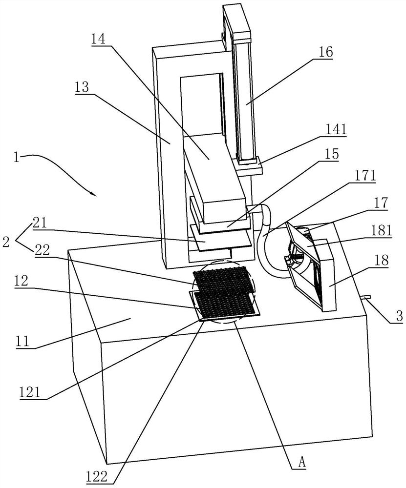
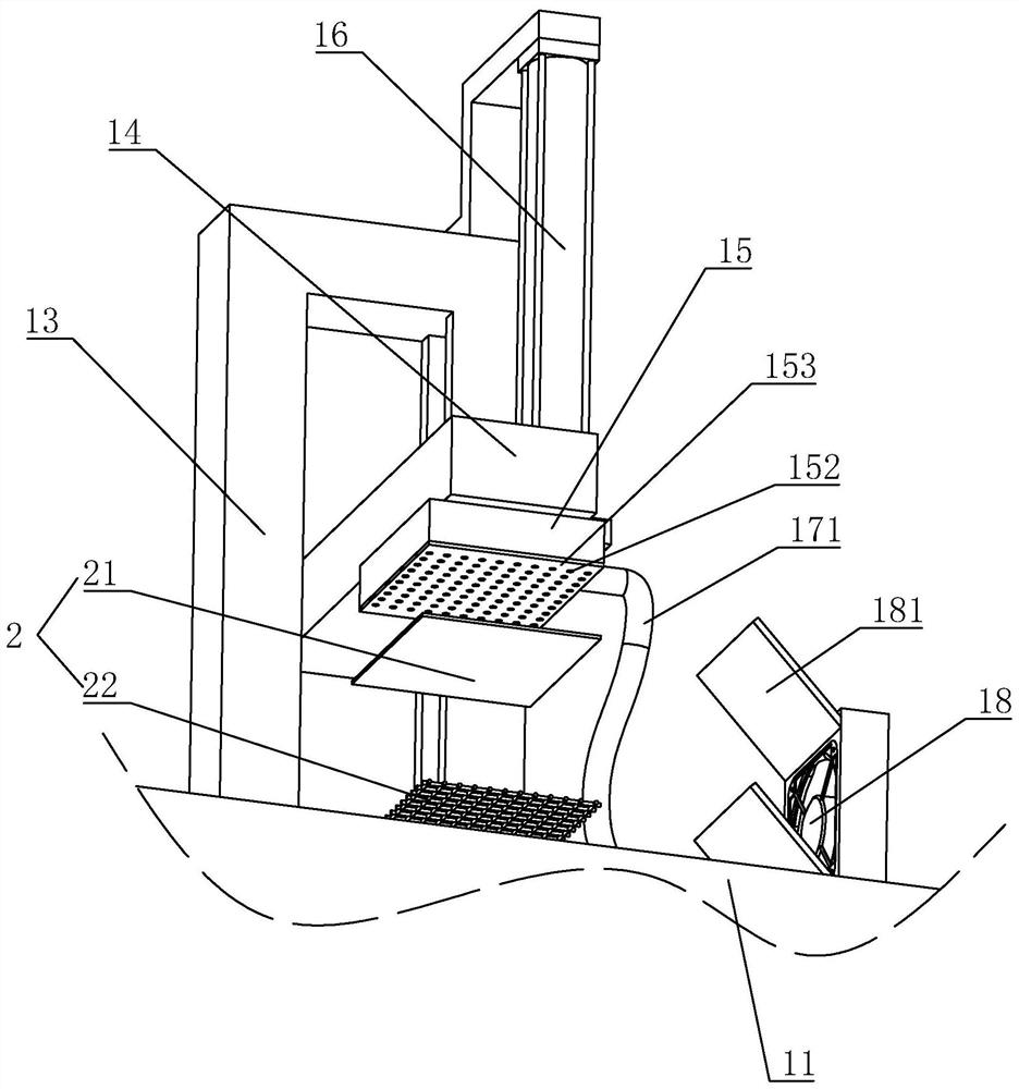
[0040] refer to figure 1 , is a kind of laser plate-making method disclosed in the present invention, comprises the following operation steps:

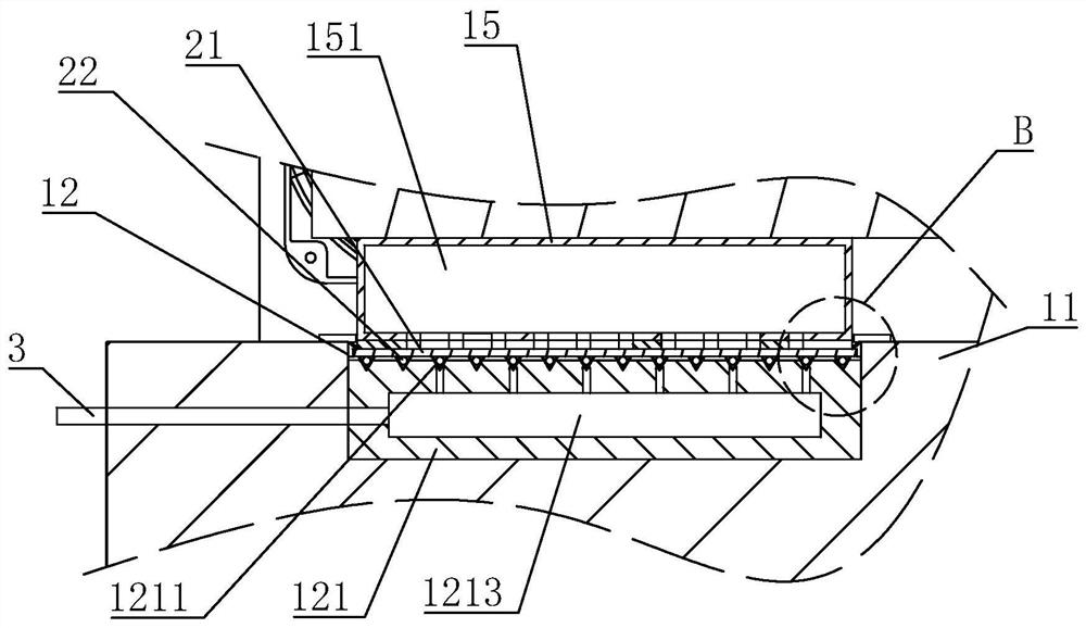
[0041]Bonding of the stencil film and the steel wire mesh: the stencil film 21 and the steel mesh 22 are bonded and fixed by the gluing and bonding integrated device 1 to obtain the screen plate 2;

[0042] refer to figure 1 , the gluing and bonding integrated device 1 used in the bonding operation steps of the plate film 21 and the steel wire mesh 22 includes a workbench 11, a support block 13 is bonded to the workbench 11, and the support block 13 is arranged along the vertical direction, Vertical sliding is provided with connecting rod 14 on the support block 13, and the support block 13 is provided with the cylinder 16 that drives the connecting rod 14 to move along the vertical direction of the support block 13. The telescopic rod of the cylinder 16 is arranged towards the connecting rod 14. In this embodiment, one side of the ...


PUM


Abstract

The invention relates to the field of screen printing, discloses a laser plate making method and equipment, and solves the technical problem of resource waste caused by the fact that a plate film anda steel wire mesh need to be cut due to non-flush butt joint in the machining process of an existing screen. The laser plate making method comprises the following steps that the plate film and the steel wire mesh are bonded, specifically, bonding and fixing the plate film and the steel wire mesh are carried out through a gluing and bonding integrated device to obtain a screen printing plate; and aprinting area is processed, specifically, the screen printing plate is placed on a screen printing plate bearing platform of laser engraving equipment, the position of the screen printing plate is adjusted by translating the screen printing plate bearing platform, and laser engraving is carried out on the plate film to form a printable area. According to the laser plate making method and the equipment, aligning and bonding the plate film and the steel wire mesh are carried out through the gluing and bonding integrated device, cutting part of the plate film and the steel wire mesh which are staggered on the edge of the screen do not need to be carried out in the later period, and resources are saved.

Description

technical field [0001] The invention relates to the technical field of screen printing, in particular to a laser plate-making method and equipment thereof. Background technique [0002] Most of the existing screen production is made by exposure and development of photosensitive glue. The surface of the mesh is covered with photosensitive glue. Printability and more stable process capabilities, the exposure method can no longer meet these various needs. [0003] The Chinese patent with the publication number CN110802912A discloses a laser plate-making method, which includes the following steps: 1) fixing the plate film on the steel wire mesh of the screen plate; 2) placing the screen plate on the screen plate carrying platform of the laser engraving equipment, through Translate the screen carrying platform to adjust the position of the screen, and laser engrave the printable area on the plate film. When the plate film and the steel mesh are combined, the plate film and the ...

Claims


Application Information

Patent Timeline
Patent Type & Authority Applications(China)
IPC IPC(8): B41C1/14
CPCB41C1/14
Inventor 张勇
Owner 无锡易杰印刷有限公司
Why Eureka
Try Eureka