[0031] The following will clearly and completely describe the technical solutions in the embodiments of the present invention with reference to the accompanying drawings in the embodiments of the present invention. Obviously, the described embodiments are only some, not all, embodiments of the present invention. Based on the embodiments of the present invention, all other embodiments obtained by persons of ordinary skill in the art without making creative efforts belong to the protection scope of the present invention.
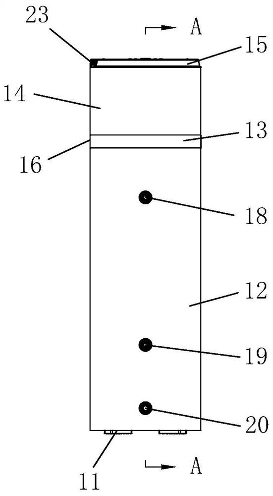
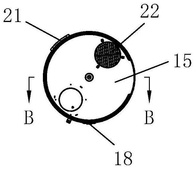
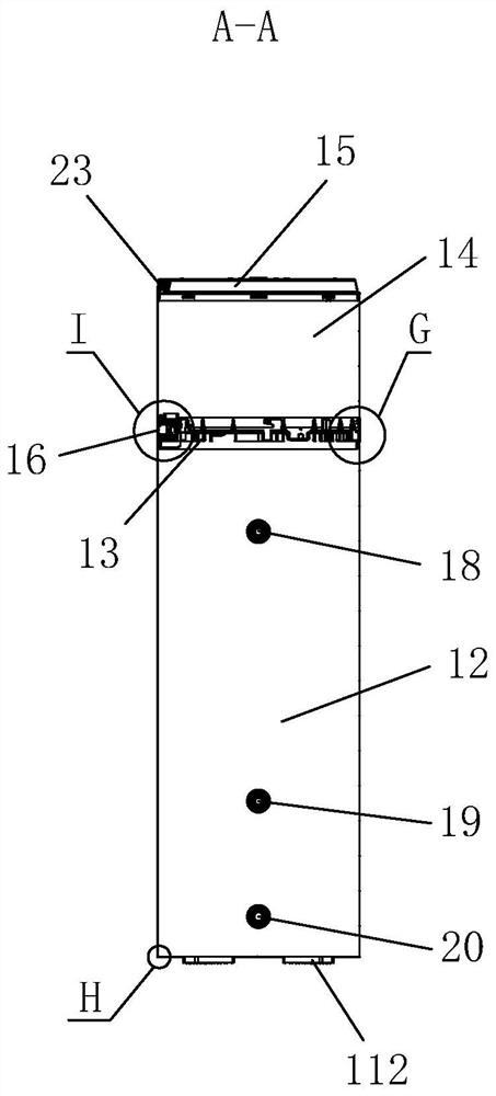
[0032] Please also refer to Figure 1 to Figure 14 , the present embodiment provides a front screwless assembled air energy water heater shell, including a base assembly 11 , a water tank shell 12 , a water tray shell 13 , a host shell 14 , a top cover shell 15 and a wire controller assembly 16 .
[0033] The base assembly 11 is installed on the bottom of the water tank shell 12; preferably, the installation structure of the base assembly 11 and the water tank shell 12 in this embodiment is as follows: image 3 and Figure 9 As shown, the bottom edge of the water tank shell 12 is provided with an inwardly turned flange 122, and the base assembly 11 is overlapped in the flange 122 in the water tank shell 12, and is fixed by foaming material. The liquid foam material has a strong viscosity, and the two can be fixed after curing. The foam material can be bonded in advance, or directly between the water tank shell and the water heater body after being installed with the water heater body. Fill the gaps with foam material for bonding.
[0034] The base assembly 11 of this embodiment is as figure 1 , image 3 , Figure 4 and Figure 9 As shown, it includes a bottom plate 111 and a plurality of bases 112, and the plurality of bases 112 are fixedly installed on the bottom of the bottom plate 111. The base serves as the support of the water heater, and a wear-resistant and corrosion-resistant rubber base can be used.
[0035] The water tray shell 13 is clamped on the top of the water tank shell 12; preferably, the installation structure of the water tray shell 13 and the water tank shell 12 in this embodiment is as follows: image 3 , Figure 4 , Figure 5 , Figure 8 , Figure 11 As shown, the top edge of the water tank shell 12 is formed with an inward-turning circular flange 124 through a necking device, and the bottom of the water tray shell 13 is provided with an undercut 132, and the water tray shell 13 and The water tank shell 12 is buckled into the circular flange 124 through the undercut 132 to be clamped and fixed. In this embodiment, the water tray shell and the water tank shell are snap-fitted. The assembly process does not require screws to be fixed, and the problem of screw corrosion will not occur. At the same time, the assembly effect is beautiful.
[0036] The host housing 14 is snap-connected to the top of the water tray housing 13; preferably, the installation structure of the host housing 14 and the water tray housing 13 in this embodiment is as follows: image 3 , Figure 4 , Figure 5 , Figure 8 , Figure 11 , Figure 13As shown, the bottom of the host casing 14 is formed with a Z-shaped necking flange 142 through necking equipment, and the Z-shaped necking flange 142 is distributed with a plurality of locking slots 140 along the circumferential direction, and the locking slots 140 is generally formed by stamping, and the inside of the top of the water tray shell 13 is provided with a buckle 134, and the host shell 14 and the water tray shell 13 are rotated into the snap slot 140 through the buckle 134 for snap connection. In this embodiment, four snap slots 140 are generally provided, and four buckles 134 are also provided relative to them. During assembly, the snap slots can be buckled into the buckles by rotating the shell of the host for locking, and the snaps are assembled. The assembly process does not need to be fixed by screws, the problem of screw corrosion will not occur, and the assembly is simple and the effect is good.
[0037] In order to realize the stability of the clamping between the main unit shell 14 and the water tray shell 13, further, in another embodiment, the water tray shell 13 is also provided with two fixing screws at the rear of both sides of the water heater shell (Fig. (not shown), the two fixing screws are threaded through the Z-shaped necking flange 142 of the water tray shell 13 and the host shell 14 . The fixing screws in this embodiment are preferably anti-rust screws. Only two fixing screws are needed to further fix the shell of the host machine and the shell of the water tray, and the screws are arranged on the back, which does not affect the appearance of the front of the water heater without screws. The quantity is small, and the overall impact on the water heater is negligible.
[0038] The top cover shell 15 is clamped on the top of the host shell 14; preferably, the installation structure of the top cover shell 15 and the host shell 14 in this embodiment is as follows: Figure 4 and Figure 10 As shown, the top edge of the host shell 14 is formed with an inwardly turned circular flange 144 through a necking device, and the bottom of the top cover shell 15 is provided with an undercut 152, and the top cover shell 15 and the host shell 14 is buckled into the circular flange 144 through the undercut 152 for clamping and fixing. In this embodiment, the clamping method of the top cover shell and the main engine shell is the same as the clamping mode of the water tank shell and the water tray shell. The clamping assembly does not require screws to be fixed during the assembly process, and the problem of screw corrosion will not occur. , At the same time the assembly effect is beautiful.
[0039] The wire controller assembly 16 is arranged on the front of the water heater casing and is fitted with the wire controller installation slot 130 of the water tray casing 13 by suction. Preferably, as image 3 , Figure 5 , Image 6 , Figure 7 As shown, the inner two ends of the wire controller installation groove 130 are provided with card slots 1300, and the inside of the card slot 1300 is interference-fitted with galvanized iron plates 17, and the wire controller assembly 16 is embedded with two strong Magnets 160, two of the powerful magnets 160 are arranged opposite to the galvanized iron plate 17, and the wire controller assembly 16 is attached to the galvanized iron plate 17 through the powerful magnets 160 for installation. The wire controller assembly in this embodiment is installed by suction and engagement with a galvanized iron plate through a strong magnet, and no screw connection is required during the installation process, and the problem of screw corrosion will not occur.
[0040] Preferably, the base assembly 11, the water tank shell 12, the water tray shell 13, the host shell 14, the top cover shell 15 and the wire controller assembly 16 of this embodiment do not protrude from the outer surface formed by the water tank shell 12 after assembly . The assembled water heater has good integrity, no convex surface on the outer surface, and beautiful appearance.
[0041] like figure 1 , Figure 4 , Figure 12 As shown, one side of the water tank shell 12 in this embodiment is provided with an outlet water pipe seat 18 , a water inlet pipe seat 19 and a sewage outlet pipe seat 20 sequentially from top to bottom, and an electric heating cover assembly 21 is provided on the other side.
[0042] Wherein, the structure and installation method of the water outlet socket 18, the water inlet socket 19 and the sewage outlet socket 20 are the same as those of the water tank shell 12, as Figure 12 As shown, take the water outlet socket 18 as an example for illustration:
[0043] The water outlet socket 18 includes a water outlet decorative cover 181 and a water outlet socket body 182, the water outlet decorative cover 181 is in interference fit with the water tank shell 12, and the water outlet socket body 182 passes through the water outlet The decorative cover 181 is interference fit with the decorative cover 181 of the water outlet.
[0044] The electric heating cover assembly 21 includes a silicone gasket 211 and an electric heating cover 212. The electric heating cover 212 is installed on the silicone gasket 211. The silicone gasket 211 fits the water tank shell 12 and is fixed to the water tank shell 12 by four screws. The water tank casing, the screws of this embodiment are treated with anti-rust treatment. Since the electric heating cover assembly is arranged on the side of the water heater, the effect of no screws on the front of the water heater is not affected.
[0045] The top cover shell 15 of this embodiment is as figure 2 and Figure 14 As shown, the top of the top cover shell 15 is provided with a protective net 22, and the protective net 22 is fixedly installed on the top cover shell 15 through three special-shaped buckles. The specific installation structure is as follows Figure 14 As shown, the top cover shell 15 is provided with a through hole 150 , and the protective net 22 is provided with a buckle 220 , and the buckle 220 is inserted into the through hole 150 for buckle installation.
[0046] Further, in order to strengthen the connection reliability between the protective net 22 and the top cover shell 15, hot melt adhesive (not shown in the figure) is poured into the through hole 150, and the protective net and the top cover can be realized after the hot melt adhesive solidifies. Tight fit of the housing.
[0047] like figure 1 and image 3 As shown, the top cover shell 15 is also provided with a nameplate 23 on the front, and the nameplate 23 is sunk and pasted on the top cover shell 15 .
[0048] A frontal screwless assembled air energy water heater based on the above-mentioned embodiments includes a water heater body, and the shell is bonded to the water heater body by foaming material.
[0049] The above descriptions are only examples of the present invention, and are not intended to limit the patent scope of the present invention. Any equivalent structure or equivalent process conversion made by using the content of the description of the present invention, or directly or indirectly used in other related technical fields, shall be The same reasoning is included within the scope of patent protection of the present invention.