
Projection screen capable of maintaining the polarization state of projection light

A technology of projection screen and maintaining projection, applied in the field of 3D display, which can solve the problems of dizziness, depolarization, and amplitude depolarization of viewers.

Pending Publication Date: 2020-09-01
SHENZHEN PHOTONIC CRYSTAL TECH CO LTD +1
View PDF0 Cites 2 Cited by
  • Summary
  • Abstract
  • Description
  • Claims
  • Application Information

AI Technical Summary

Problems solved by technology

[0005] Second, amplitude depolarization
[0006] Third, geometric depolarization
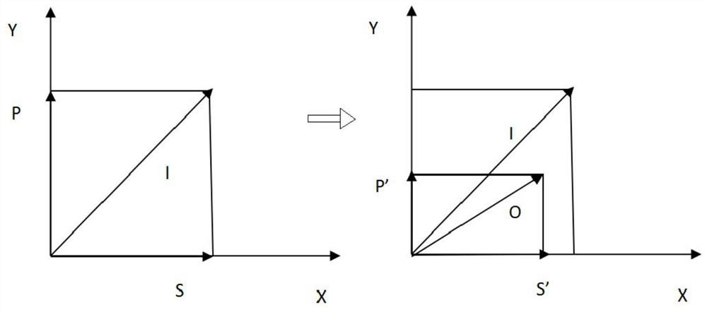
[0007] The current 3D projection screens have a certain depolarization of reflected light, especially in the case of large angles: for example, the image projected by the projector for the left eye has a specific polarization direction, such as left-handed light, when it is projected into 3D When projecting a screen, based on the half-wave delay, most of the reflected light is right-handed circularly polarized light, and a small part becomes left-handed circularly polarized light due to depolarization, which changes the polarization state of the projected light on the screen. Not only can you see the image of the right eye, but also a small part of the image of the left eye, which will produce double images on the screen, and the viewer will easily feel dizzy, which greatly reduces the viewing experience of the 3D theater
At present, the general 3D projection screen has a polarization retention ratio of only 100:1, that is, 1% of the polarized light of the left eye image becomes another polarization, which is seen by the right eye, and the user experience is not good.

Method used


Image

  • Projection screen capable of maintaining the polarization state of projection light
  • Projection screen capable of maintaining the polarization state of projection light
  • Projection screen capable of maintaining the polarization state of projection light

Examples


Embodiment Construction

[0027] The present invention will be described in detail below in conjunction with the accompanying drawings and specific embodiments.

[0028] This embodiment provides a projection screen capable of maintaining the polarization state of projected light, such as Figure 4 As shown, the shown projection screen includes several projection screen units, for example, including projection screen unit 401 , projection screen unit 402 , projection screen unit 403 , projection screen unit 404 and so on.

[0029] And, each of the projection screen units includes at least two layers of optical layered structures, wherein each of the projection screen units may include two layers of optical layered structures, or three layers of optical layered structures, or more Layered optical layered structure; in the projection screen units, the number of layers of the optical layered structure generally included between the projection screen units is the same.

[0030] Wherein, the optical layered...


PUM

PropertyMeasurementUnit
angleaaaaaaaaaa

Abstract

The invention discloses a projection screen capable of maintaining the polarization state of projection light, and the projection screen comprises a plurality of projection screen units, each projection screen unit comprises at least two layers of optical layered structures, and the phase change of each optical layered structure can be compensated by other layers. Each layer of optical layered structure is made of an optical dielectric film and / or a metal film. According to the invention, at least two layers of optical layered structures are arranged, material selection and thickness design are carried out on a medium forming each layer of optical layered structure, and a phase compensation effect can be achieved, change of the phase and the amplitude generated by one layer of the opticallayered structure can be compensated by the other layers of the optical layered structures, so that the polarization state of emergent light and the polarization state of incident light can be kept consistent, the polarization maintaining rate can reach 200:1 to 2000:1 or above, and the typical polarization maintaining rate is 1000:1, the double images of the 3D movie can be greatly eliminated, the dizziness is reduced, and the 3D movie watching experience is improved.

Description

technical field [0001] The invention relates to the technical field of 3D display, in particular to a projection screen capable of maintaining the polarization state of projected light. Background technique [0002] 3D cinema provides people with a viewing experience closer to reality, and it has become the mainstream of cinema in recent years. The realization of 3D cinema is generally to use one or two projectors, by adding polarizers or polarization conversion devices, to project pictures for the left eye and right eye respectively. The left and right eye images have different polarization states, the screen scatters and reflects the light from the projector, and the viewer wears polarized glasses to distinguish the images for the left eye and the right eye, so that the left eye only sees the left eye image, and the right eye only sees the right eye image. Eye images, the human brain is constantly processing the images seen by the left and right eyes, creating a three-dim...

Claims


Application Information

Patent Timeline
Patent Type & Authority Applications(China)
IPC IPC(8): G03B21/604G03B21/60
CPCG03B21/60G03B21/604
Inventor 王勇竞郑港张喜玉周永业
Owner SHENZHEN PHOTONIC CRYSTAL TECH CO LTD
Learn More