Clamp de-embedding method and system, storage medium, computer program and application

A computer program and de-embedding technology, applied in computer-aided design, calculation, special data processing applications, etc., can solve problems such as large calculation errors, large parasitic parameters, and difficult processing of calibration parts, and achieve low processing and manufacturing requirements. The effect of low processing accuracy requirements and good application value

Active Publication Date: 2020-09-01
XIDIAN UNIV
View PDF3 Cites 4 Cited by
  • Summary
  • Abstract
  • Description
  • Claims
  • Application Information

AI Technical Summary

Problems solved by technology

[0004] To sum up, the existing problems in the prior art are: traditional de-embedding and calibration methods require multiple standard calibration parts, which leads to: 1. The calculation method is very complicated , including 8 to 12 error models; 2. The measurement accuracy is directly related to the accuracy of the standard parts, so it puts forward extremely high requirements for the design and processing precision of the calibration parts; 3. Open circuit, short circuit, load calibration parts The processing is difficult and costly, which often brings large parasitic parameters; 4. The calculation error is large and difficult to eliminate
[0005] Difficulties in solving the above technical problems: If the traditional de-embedding and calibration methods are still used, 1. The complexity of the calculation method cannot be solved; 2. The improvement of measurement accuracy and The reduction of error can only be achieved by improving the processing technology and processing precision, which puts forward higher requirements for processing instruments, which cannot be realized in the short term

Method used


Image

  • Clamp de-embedding method and system, storage medium, computer program and application
  • Clamp de-embedding method and system, storage medium, computer program and application
  • Clamp de-embedding method and system, storage medium, computer program and application

Examples


Embodiment Construction

[0052] In order to make the object, technical solution and advantages of the present invention more clear, the present invention will be further described in detail below in conjunction with the examples. It should be understood that the specific embodiments described here are only used to explain the present invention, not to limit the present invention.

[0053] Aiming at the problems existing in the prior art, the present invention provides a fixture de-embedding method, system, storage medium, computer program and application. The present invention will be described in detail below with reference to the accompanying drawings.

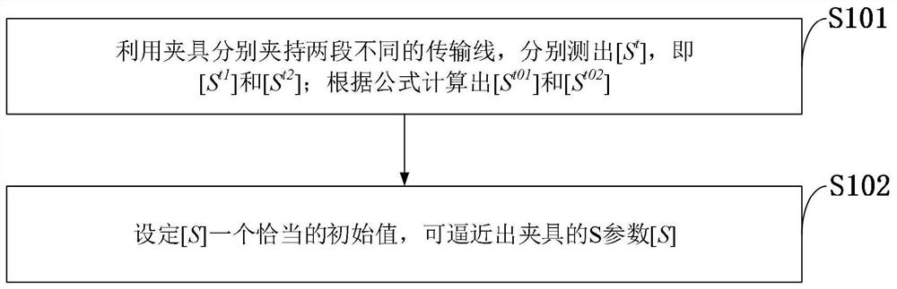
[0054] Such as figure 1 As shown, the fixture de-embedding method provided by the embodiment of the present invention includes the following steps:

[0055]S101: Use the fixture to hold two different transmission lines respectively, and measure [S t ], namely [S t1 ] and [S t2 ]; calculated according to the formula [S t01 ] and [S t02 ];

[0...


PUM


Abstract

The invention belongs to the technical field of microwave testing, and discloses a clamp de-embedding method and system, a storage medium, a computer program and application, and the method comprisesthe steps: employing a clamp to clamp two different transmission lines, and respectively measuring S parameters [St], i.e. [St1] and [St2], of the whole system; calculating S parameters [St01] and [St02] of the two different sections of transmission lines clamped by the clamp according to a formula; setting an appropriate initial value [S], and approximating the S parameter [S] of the clamp. The comparison between the clamp simulation data and the calculation data finds that the clamp S parameter data at the two ends of the tested piece can be accurately and effectively extracted by adopting the clamp de-embedding method of the double transmission lines, and a good foundation is laid for subsequent semiconductor parameter testing. Compared with a traditional calibration method, the methodhas the advantages of being easy to implement and machine and low in requirement for the machining precision of standard parts, and has good application value.

Description

technical field [0001] The invention belongs to the technical field of microwave testing, and in particular relates to a fixture de-embedding method, system, storage medium, computer program and application. Background technique [0002] At present, in the design and development of microwave circuits, the testing of microwave devices has always been taken seriously. Due to the development of CAD technology, the measurement accuracy requirements of microwave devices are gradually increasing. The port of the automatic network analyzer often cannot be directly connected to the DUT, but needs to pass a specific fixture to measure the DUT. Therefore, the parameters obtained by the microwave network analyzer include information on both the DUT and the fixture. In order to obtain only the accurate parameters of the device under test, it is necessary to perform de-embedding calculations to eliminate the influence of the fixture. [0003] Traditional de-embedding calibration method...

Claims


Application Information

Patent Timeline
Patent Type & Authority Applications(China)
IPC IPC(8): G06F30/398G01R31/00
CPCG06F30/398G01R31/00Y02E60/00
Inventor 詹劲松孙璐岳春宇姜子涵王家礼
Owner XIDIAN UNIV
Why Eureka
Try Eureka