Eureka AIR delivers breakthrough ideas for toughest innovation challenges, trusted by R&D personnel around the world.

New energy battery cover plate assembly

A battery cover, new energy technology, applied in battery pack components, electrical components, secondary batteries, etc., can solve the problems of poor internal heat dissipation, troublesome disassembly and assembly, and no shock absorption effect on the cover, and achieve heat dissipation effect. Good, not easy to heat agglomeration effect

Inactive Publication Date: 2020-09-01
耿凤玲
View PDF0 Cites 4 Cited by
  • Summary
  • Abstract
  • Description
  • Claims
  • Application Information

AI Technical Summary

Problems solved by technology

[0003] At present, the lithium battery cover plate is generally fixed by screws, which is troublesome to disassemble and assemble. The cover plate has no shock absorption effect, and the bumps in the car can easily make the interior loose and damaged. At the same time, the internal heat dissipation effect is poor, which easily leads to heat accumulation, resulting in safety accidents. And the problem of component damage, therefore, a new energy battery cover assembly is proposed to solve the problem

Method used


Image

  • New energy battery cover plate assembly
  • New energy battery cover plate assembly
  • New energy battery cover plate assembly

Examples


Embodiment

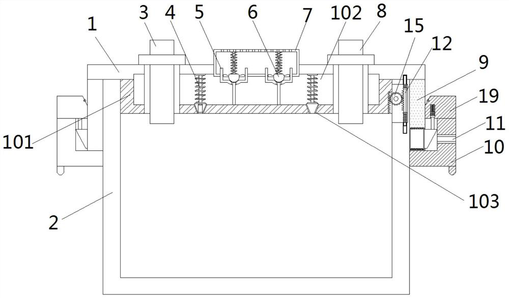
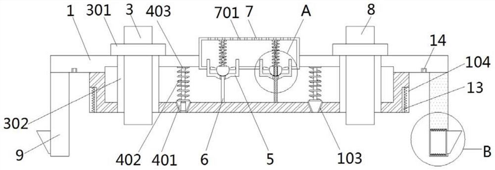
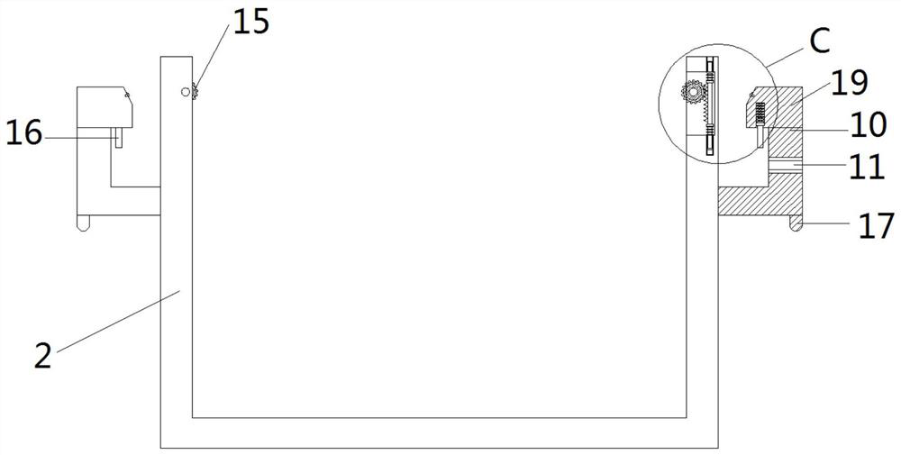
[0032] As attached figure 1 Attached Picture 9 Shown: a new energy battery cover plate assembly, including a cover plate 1, a battery box 2, a positive pole 3, a pole base 301, an insulating sleeve 302, and a negative pole 8. The upper ends of the left and right sides of the battery box 2 are fixedly connected with L-shaped support plate 10, the top of L-shaped support plate 10 is fixedly connected with stopper assembly 19, the upper and lower ends of the left and right sides of the battery box 2 are equipped with No. 2 grooves 201, and the inside of the No. 2 groove 201 is close to the center of the battery box 2. A shaft is transferred between the front and rear of the upper end of one side, and the center of the shaft is fixedly connected with a gear 15, and the center of the upper and lower ends of the second groove 201 away from the center of the battery box 2 is provided with the second slot 203 and the first socket respectively. The rack assembly 12 is movably connected ...


PUM


Abstract

The invention provides a new energy battery cover plate assembly. The new energy battery cover plate assembly comprises a cover plate and a battery box, and L-shaped supporting plates are fixedly connected to the upper ends of the left and right sides of the battery box; and the top of each L-shaped supporting plate is fixedly connected with a stop block assembly. Second grooves are formed in thefront and back of the upper ends of the left and right sides in the battery box; a rotating shaft is rotationally connected between the front and rear sides of the upper end of one side close to the centers of the battery boxes in the second grooves; a gear is fixedly connected to the center of the rotating shaft; the positive pole and the negative pole are sleeved and fixed with a pole base at the upper end of the cover plate; the upper ends, located in the first hollow groove, of the positive pole and the negative pole are sleeved and fixed with insulating sleeves; and first grooves are formed in the front and back of the lower ends of the left and right sides of the sealing block. The bottoms of the first groovesarein a notch shape, second racksarefixedly connected into the first grooves, and limiting holes are formed in the positions, located between the sealing blocks and the side plates, of the front end and the rear end of the bottom of the cover plate. The new energy battery cover plate assembly provided by the invention can solve the problems that an existing new energy battery cover plate assembly is trouble in dismounting and mounting and cannot meet the requirements ofnew energy batteries.

Description

Technical field [0001] The invention relates to the technical field of new energy batteries, in particular to a new energy battery cover plate assembly. Background technique [0002] With the development of new energy vehicles, there are more and more innovations in new energy vehicle batteries. New energy vehicle batteries are new types of vehicles that use new energy technologies to reduce "greenhouse gas" emissions. The batteries are becoming increasingly hot in the development of new energy. Lithium-ion power batteries, as the power components of electric vehicles, are favored and valued by major new energy research institutions and vehicle manufacturers. [0003] At present, the lithium battery cover is generally fixed by screws, which is troublesome to disassemble and assemble. The cover does not have the shock absorption effect. The bumps in the car can easily make the interior loose and damage. At the same time, the internal heat dissipation effect is poor, which can easily...

Claims


Application Information

Patent Timeline
IPC IPC(8): H01M2/04H01M2/10H01M2/12H01M10/613H01M10/625H01M10/6556H01M10/6563
CPCH01M10/613H01M10/625H01M10/6556H01M10/6563Y02E60/10
Inventor 耿凤玲
Owner 耿凤玲
Why Eureka
Eureka Blog
Learn More