
Sliding top pressure type electronic heat dissipation device

A heat-dissipating device and electronic technology, which is applied in the direction of modification, cooling/ventilation/heating transformation through conduction heat transfer, etc., can solve the problems of overall scrapping, deformation of heat-dissipating device, low heat-dissipating efficiency, etc., and achieve fast installation, rapid heat dissipation, and use Flexible and convenient effects

Inactive Publication Date: 2020-09-01
江苏海鼎电气科技有限公司
View PDF0 Cites 0 Cited by
  • Summary
  • Abstract
  • Description
  • Claims
  • Application Information

AI Technical Summary

Problems solved by technology

The existing traditional water-cooled radiator is to open a straight groove on the base, then seal and weld the upper cover plate and the base together, and install electronic devices in the heat dissipation area at the upper end of the upper cover plate. Due to the impact of cold shrinkage, the heat sink will be deformed. Because it is a tidy structure, it will be scrapped as a whole. Therefore, it is necessary to develop an electronic heat sink that is very convenient to install and disassemble for easy replacement of accessories; in addition, due to the different electronic devices The working time may be different, and the heat dissipation method of the base is a direct integral heat dissipation, and the electronic components that are not in the working state and do not need heat dissipation are also radiating heat, which results in low heat dissipation efficiency. Separate control of areas requiring heat dissipation and areas requiring heat dissipation has also become the focus of research and development of the present invention

Method used


Image

  • Sliding top pressure type electronic heat dissipation device
  • Sliding top pressure type electronic heat dissipation device
  • Sliding top pressure type electronic heat dissipation device

Examples


Embodiment Construction

[0019] The content of the present invention will be further described in detail below in conjunction with the accompanying drawings.

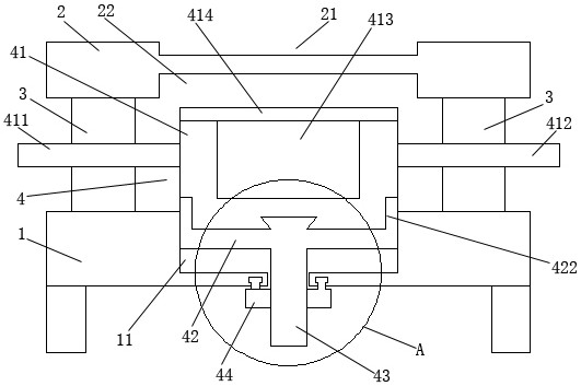
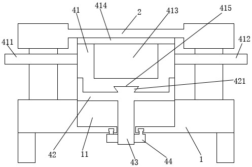
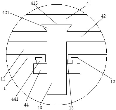
[0020] Such as Figures 1 to 4 As shown, a sliding top-pressure electronic cooling device includes an upper mounting plate 2, a connecting plate 3, a lower support seat 1, and a heat dissipation mechanism 4; the upper mounting plate 2 and the lower support seat 1 are arranged in parallel up and down; A sliding gap 5 is provided between the upper mounting plate 2 and the lower support base 1; a plurality of heat dissipation areas 21 are provided on the upper end of the upper mounting plate 2; The connecting plate 3; the middle of the upper end of the lower support seat 1 is provided with a floating groove 11 of a strip structure; the middle of the lower end of the floating groove 11 is provided with a connecting hole 13; the heat dissipation mechanism 4 includes a floating frame 42 , a floating threaded post 43, a drive nut 44, and a cooling bl...


PUM


Abstract

The invention discloses a sliding top pressing type electronic heat dissipation device which comprises an upper mounting plate, a connecting plate, a lower supporting seat and a heat dissipation mechanism. Rapid heat dissipation is achieved, the whole process is convenient to operate and rapid to install, an independent heat dissipation structure can be achieved, and use is flexible and convenient.

Description

technical field [0001] The invention relates to a sliding top-pressure electronic cooling device. Background technique [0002] The requirements for reliability, performance index, and power density of modern electronic equipment are further improved, and the thermal design of electronic equipment is becoming more and more important. Power devices are key devices in most electronic equipment, and their working status directly affects the reliability, safety and service life of the whole machine. In addition to effectively dissipating heat, the heat dissipation solution of power devices is also crucial to reliability. The existing traditional water-cooled radiator is to open a straight groove on the base, then seal and weld the upper cover plate and the base together, and install electronic devices in the heat dissipation area at the upper end of the upper cover plate. Due to the impact of cold shrinkage, the heat sink will be deformed. Because it is a tidy structure, it wi...

Claims


Application Information

Patent Timeline
Patent Type & Authority Applications(China)
IPC IPC(8): H05K7/20
CPCH05K7/2039
Inventor 陶勇
Owner 江苏海鼎电气科技有限公司
Learn More