Scientific and technological intelligent seeding device integrating hole digging and seeding

A kind of seeding device and technological technology, applied in the field of scientific and technological services, can solve the problems of low degree of automation and no function of digging holes, and achieve the effects of improving work efficiency, increasing diversity, and increasing linkage

Inactive Publication Date: 2020-09-04
GUANGZHOU RUIYIN TECH CO LTD
9 Cites 4 Cited by

AI-Extracted Technical Summary

Problems solved by technology

[0003] Agriculture is an important industrial sector in the national economy, and China's development has reached a critical stage. Only by relying on innovation and development can we solve the current problems, develop the technology service industry, and provide strong support for innovation-driven development, so that China's economic development can be healthy and Orderly and strong development, in the process of agricultural development, it is very important for all aspects of agricultural production. For agricultural seeding, there are generally two methods, one mainly relies on manual operation , it is necessary to dig holes first, and then sow in turn. The other is to use a seeder to operate, but ...

Abstract

The invention relates to the technical field of science and technology service and discloses a scientific and technological intelligent seeding device integrating hole digging and seeding. The seedingdevice comprises a storage box used for storing seeds, through cooperative use of the storage box, a baffle, connecting rods and a sector gear, the storage box can be automatically opened during holedigging, so that synchronous seeding is realized, the opening and closing time of the storage box is kept consistent, and quantitative seeding can be realized; through cooperative use of a third connecting rod, a threaded rod, a second rotating wheel, a first connecting rod and a second connecting rod, manual hole digging can be simulated, manual operation is not required, so that the working efficiency during planting is improved, the hole digging depth can be changed as required, and the diversity of planter functions is improved; and through cooperative use of a first gear, a half gear, aloop bar and the rotating disc, the hole digging and seeding steps can be linked, so that the linkage of the whole device is improved, and the device is simpler to operate.

Application Domain

PlantingFurrow making/covering +1

Technology Topic

Agricultural engineeringThreaded rod +2

Image

  • Scientific and technological intelligent seeding device integrating hole digging and seeding
  • Scientific and technological intelligent seeding device integrating hole digging and seeding
  • Scientific and technological intelligent seeding device integrating hole digging and seeding

Examples

  • Experimental program(1)

Example Embodiment

[0023] The following will clearly and completely describe the technical solutions in the embodiments of the present invention with reference to the accompanying drawings in the embodiments of the present invention. Obviously, the described embodiments are only some, not all, embodiments of the present invention. Based on the embodiments of the present invention, all other embodiments obtained by persons of ordinary skill in the art without making creative efforts belong to the protection scope of the present invention.
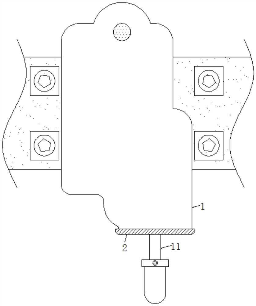
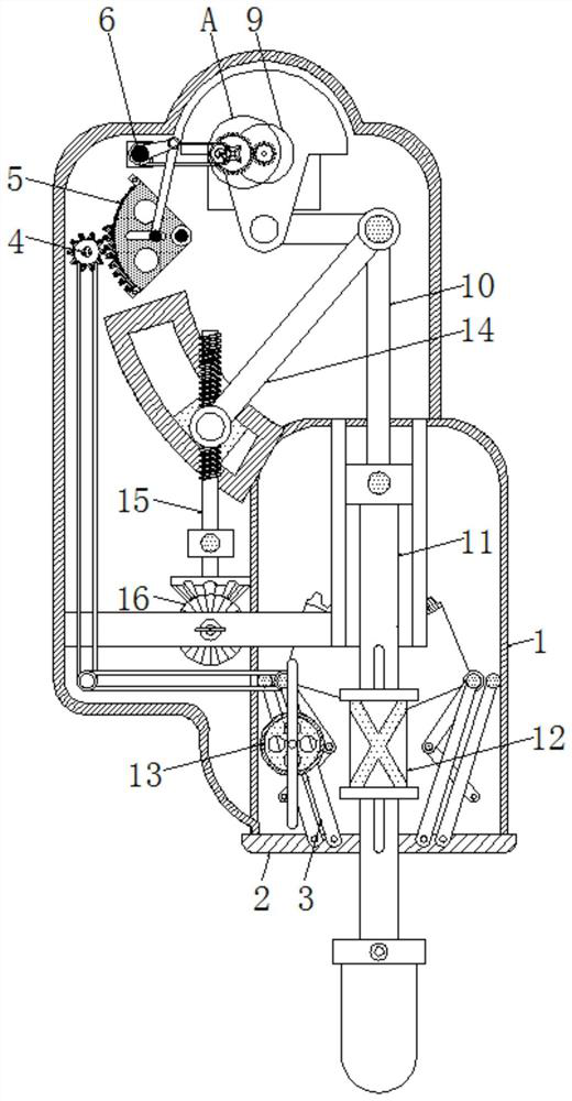
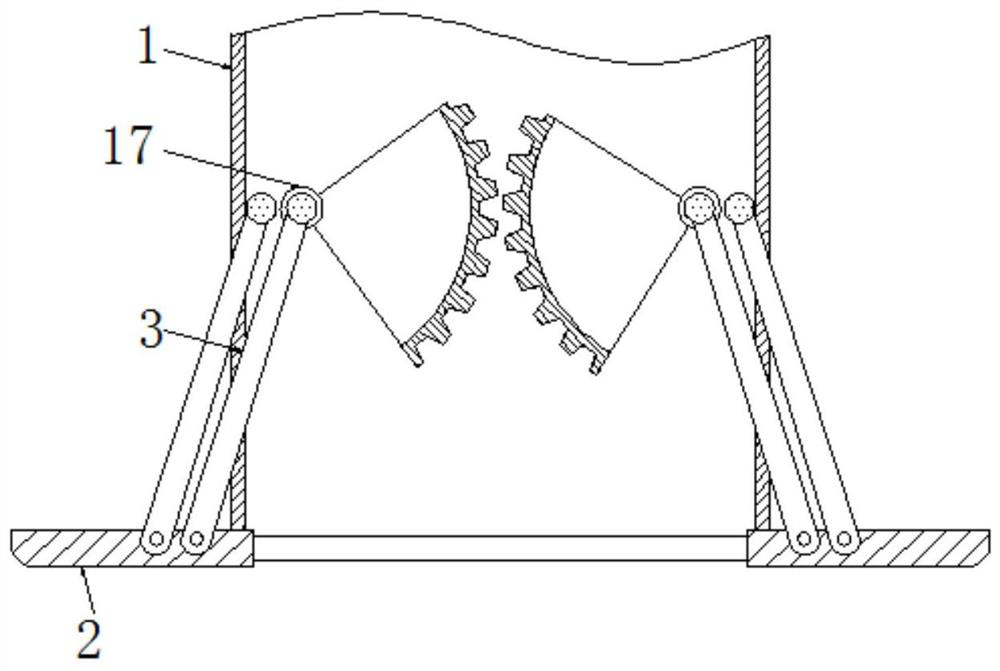
[0024] see Figure 1-4 , a technological intelligent sowing device integrating digging and sowing, including a storage box 1, using the storage box 1 to store seeds, the bottom of the storage box 1 is movably connected to a baffle 2, and the baffle 2 is provided with two The specifications of the two baffles 2 are the same, and they are distributed symmetrically with reference to the center line of the storage box 1. The movement of the baffles 2 is used to control the opening and closing of the storage box 1, so as to achieve the purpose of automatic seeding. The outer side of the baffle 2 is movably connected with a connecting rod 3, and the movement of the connecting rod 3 drives the baffle 2 to move synchronously. The outer side of the connecting rod 3 is movably connected with a first gear 4, and the rotation of the first gear 4 drives the sector gear 17 Rotate synchronously, the right side of the first gear 4 is movably connected with a half gear 5, when the half gear 5 rotates, it will drive the first gear 4 to rotate synchronously, the outside of the half gear 5 is provided with a chute, and the outside of the chute Teeth are provided, and the size of the teeth is adapted to the size of the first gear 4, so that the teeth can move along the chute, so that the teeth can move along the half gear 5, when the movement process It will drive the first gear 4 to rotate clockwise and counterclockwise intermittently. There is a disk under the first gear 4. The disk is connected to the first gear 4 through a belt, so it will drive the disk synchronously. Rotate, the disk and the sector gear 17 are also movably connected by a belt, so the sector gear 17 will eventually be driven to rotate clockwise and counterclockwise synchronously and intermittently. The outer side of the half gear 5 is movably connected with the first rotating rod 6, and A rotating rod 6 and the half gear 5 are flexibly connected through a strut, so when the first rotating rod 6 rotates, it will drive the half gear 5 to swing synchronously.
[0025] The right side of the first rotating rod 6 is movably connected with the first runner 7, and when the first runner 7 rotates, it will drive the special-shaped disc 8 to rotate synchronously, and the back side of the first runner 7 is provided with a disc, and the disc It is movably connected with the disc set on the back of the first rotating rod 6 through a belt, and a fixed rod is arranged on the outside of the first rotating wheel 7. When the first rotating rod 6 rotates, it will drive the first rotating wheel 7 to rotate synchronously. , thereby driving the fixed rod to rotate synchronously, the right side of the first runner 7 is movably connected with a special-shaped disk 8, and the surface of the special-shaped disk 8 is provided with a chute, and the size of the chute is the same as the size of the fixed rod on the outside of the first runner 7 Adapt to each other, the back of the special-shaped disc 8 is concentrically provided with a large gear, and the outer side of the second runner 9 is concentrically provided with a pinion, and the size of the pinion and the size of the bull gear are mutually adapted. The rotation drives the second runner 9 to rotate clockwise and counterclockwise synchronously and intermittently. The outer side of the special-shaped disc 8 is movably connected with the second runner 9 , and the outer side of the second runner 9 is movably connected with the first connecting rod 10 . When a connecting rod 10 moves, it will drive the second connecting rod 11 to move synchronously. The lower end of the first connecting rod 10 is movably connected with the second connecting rod 11, and the outer side of the second connecting rod 11 is movably connected with the sleeve rod 12, and the sleeve rod The right side of 12 is movably connected with rotating disk 13, and the surface of rotating disk 13 is provided with fixed rod, and the surface of sleeve rod 12 is provided with chute, and the size of its chute and the size of fixed rod are adapted mutually, when rotating disk 13 rotates, can In contact with the chute, it finally drives the sleeve rod 12 to rotate clockwise and counterclockwise synchronously and intermittently, thereby driving the second connecting rod 11 to move to the bottom and then synchronously intermittently clockwise and counterclockwise. The second connecting rod 11 is set below There is a shovel, so as to simulate manual digging automatically, the outside of the first connecting rod 10 is movably connected with a third connecting rod 14, and the side of the third connecting rod 14 away from the first connecting rod 10 is movably connected with a threaded rod 15, The surface of the threaded rod 15 is provided with threads, and the inside of the threaded rod 15 is provided with a slide block that is compatible with the thread size. The outer side of the threaded rod 15 is movably connected with a rotary knob 16, and the side of the connecting rod 3 away from the baffle plate 2 is movable. Connected with sector gear 17, there are two sector gears 17, the specifications of the two sector gears 17 are the same, and they mesh with each other, thereby driving the two sector gears 17 to rotate synchronously, thereby driving the two baffle plates 2 to move synchronously, completing Automatic seeding.
[0026]Working principle: by movably connecting the output shaft of the motor with the first rotating rod 6, the first rotating rod 6 will be driven to rotate. The discs are connected by belts, so the first runner 7 will be driven to rotate synchronously. The outer side of the first runner 7 of the first runner 7 is provided with a fixed rod, so it will drive the fixed rod to rotate synchronously. When the fixed rod rotates until it coincides with the groove provided on the surface of the special-shaped disk 8, it will drive the special-shaped disk 8 to rotate synchronously, and continue to rotate. The fixed rod is far away from the groove. 8 intermittently rotates clockwise and counterclockwise, the back of the special-shaped disc 8 is concentrically provided with a large gear, and the outer side of the second runner 9 is concentrically provided with a pinion, and the size of the pinion is compatible with the size of the large gear, The rotation of the first runner 7 is used to drive the second runner 9 to rotate clockwise and counterclockwise synchronously and intermittently. The rods 10 move synchronously, and the outer side of the first connecting rod 10 is movably connected with the second connecting rod 11, which will eventually drive the second connecting rod 11 to move up and down and reciprocate intermittently synchronously, and the turntable 13 and the first runner 7 pass through The belt is movably connected, so it will drive the turntable 13 to rotate synchronously. The surface of the turntable 13 is provided with a fixed rod, and the surface of the sleeve rod 12 is provided with a chute. The size of the chute is adapted to the size of the fixed rod. When the turntable 13 rotates will contact with the chute, and finally drive the sleeve rod 12 to rotate synchronously and intermittently clockwise and counterclockwise, thereby driving the second connecting rod 11 to move to the bottom and synchronously intermittently clockwise and counterclockwise, the second connecting rod 11 A shovel is arranged below, so as to simulate manual digging automatically, and when the planting depth needs to be changed, the rotary knob 16 can be turned, and the back of the rotary knob 16 is provided with a bevel gear, and the rotary knob 16 and the bevel gear mesh with each other , so it will drive the bevel gear to rotate synchronously. The bevel gear is arranged on the outside of the threaded rod 15, and the inside of the threaded rod 15 is provided with a slider. Thread, so it will drive the slider to move synchronously, thereby changing the position of the third connecting rod 14 and the first connecting rod 10, similarly, will eventually change the distance of the second connecting rod 11 to reciprocate intermittently up and down, so as to achieve the purpose of changing the planting depth Purpose.
[0027] At the same time, when the first rotating rod 6 rotates, it will drive the half gear 5 to swing synchronously. The outer side of the half gear 5 is provided with a chute, and the outer side of the chute is provided with teeth, and the size of the teeth is the same as that of the first chute. The size of a gear 4 is adapted to each other, so that the teeth can move along the chute, so that the teeth will move along the half gear 5, and the first gear 4 will be driven intermittently and clockwise during the movement. Rotating counterclockwise, a disk is arranged below the first gear 4, and the disk is movably connected to the first gear 4 through a belt, so it will drive the disk to rotate synchronously, and the disk and the sector gear 17 are also passed through The belt is movably connected, so it will eventually drive the sector gear 17 to rotate clockwise and counterclockwise synchronously and intermittently. The outer side of the sector gear 17 is movably connected to the connecting rod 3, so it will drive the two connecting rods 3 to move synchronously, and the connecting rod 3 is far away from the One side of the sector gear 17 is movably connected with a baffle 2, which finally drives the two baffles 2 to move synchronously to both sides, so that the storage box 1 is automatically opened, and the opening time is consistent each time, and it is automatically closed after opening. Thereby, automatic seeding is completed.
[0028] Although the embodiments of the present invention have been shown and described, those skilled in the art can understand that various changes, modifications and substitutions can be made to these embodiments without departing from the principle and spirit of the present invention. and modifications, the scope of the invention is defined by the appended claims and their equivalents.

PUM

no PUM

Description & Claims & Application Information

We can also present the details of the Description, Claims and Application information to help users get a comprehensive understanding of the technical details of the patent, such as background art, summary of invention, brief description of drawings, description of embodiments, and other original content. On the other hand, users can also determine the specific scope of protection of the technology through the list of claims; as well as understand the changes in the life cycle of the technology with the presentation of the patent timeline. Login to view more.

Similar technology patents

Automatic device for welding and detecting lithium battery

ActiveCN103904367AShorten the running distanceImprove work efficiency
Owner:DONGGUAN HONBRO LI BATTERY EQUIP TECH

Vacuum cleaner

InactiveCN103356140Aprevent liftingImprove work efficiency
Owner:SUZHOU HAAN TECH +1

Classification and recommendation of technical efficacy words

  • increase diversity
  • Improve work efficiency

Recommendation Systems

InactiveUS20100268661A1increase diversity
Owner:B7 INTERACTIVE LLC

Personalized recommendation method based on commodity property entropy

InactiveCN102411754AKeep recommended hitsincrease diversity
Owner:NANJING UNIV

Indoor positioning method and positioning system

InactiveCN106289257Aincrease diversityInhibit the accumulation of errors
Owner:CHIGOO INTERACTIVE TECH

Cooperation service platform facing different source data

InactiveCN101174957AImprove management level and qualityImprove work efficiency
Owner:NANJING UNIV OF FINANCE & ECONOMICS

Screw drilling tool, vertical drilling tool testing method and well inclination simulation testing equipment

InactiveCN111594144AReduced height requirementsImprove work efficiency
Owner:DEZHOU UNITED GASOLINEEUM MACHINERY

Method for intelligent automatic identification of transmission circuit parts

Owner:INFORMATION COMM COMPANY STATE GRID SHANDONG ELECTRIC POWER +2

Keyboard spill-proofing mechanism

ActiveUS7030330B2minimize manufacturing costimprove work efficiency
Owner:LITE ON SINGAPORE PTE LTD
Why Eureka
Try Eureka