
Medical nursing instrument disinfection apparatus

A technology for disinfection devices and nursing appliances, which is applied in the direction of disinfection, heating devices, water supply devices, etc., can solve the problems of low work efficiency and poor safety, and achieve the effects of convenient insertion and removal, labor saving, and convenient use

Inactive Publication Date: 2020-09-04
李年花
View PDF8 Cites 6 Cited by
  • Summary
  • Abstract
  • Description
  • Claims
  • Application Information

AI Technical Summary

Problems solved by technology

[0005] In order to overcome the shortcomings of low work efficiency and poor safety when cleaning and disinfecting medical instruments, the technical problem to be solved is: to provide a method with high work efficiency, which does not require manual insertion of hands into the equipment to take out medical instruments, and is safe. High medical care equipment disinfection device

Method used


Image

  • Medical nursing instrument disinfection apparatus
  • Medical nursing instrument disinfection apparatus
  • Medical nursing instrument disinfection apparatus

Examples


Embodiment 1

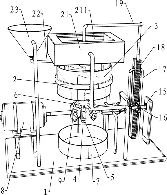
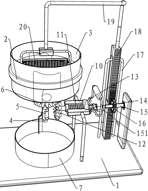
[0019] A device for disinfecting medical care appliances, such as Figure 1-3 As shown, it includes a mounting frame 1, a cleaning assembly, a power assembly and a placement assembly. The cleaning assembly is cleaned by rotating in the middle of the top of the mounting frame 1. A power assembly that provides power by rotating is installed on the mounting frame 1. Install Placement components are installed on the rack 1 .

[0020] like figure 1 and 3 As shown, the cleaning assembly includes an annular slide rail 2, a cleaning cylinder 3, a water outlet pipe 4, a valve 5, a first bevel gear 6, and a collection cylinder 7. The upper part of the installation frame 1 is welded with an annular slide rail 2, and the inner side of the annular slide rail 2 The sliding type is equipped with a cleaning cylinder 3, the middle of the bottom of the cleaning cylinder 3 is fixed with a water outlet pipe 4 through bolts, the water outlet pipe 4 is provided with a valve 5, and the top of the ...

Embodiment 2

[0028] On the basis of Example 1, such as figure 1 As shown, it also includes a feeding pipe 22 and a storage hopper 23. The front side of the left part of the installation frame 1 is welded with a storage hopper 23. The bottom of the storage hopper 23 is welded with a feeding pipe 22. The tail end of the feeding pipe 22 is located at the cleaning cylinder 3 Inside.

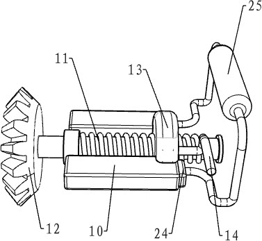
[0029] like figure 2 As shown, it also includes a clamping block 24 and a special-shaped pull rod 25. The mounting block 10 is slidably provided with a clamping block 24, and a special-shaped pull rod 25 is welded between the right ends of the clamping blocks 24.

[0030] The working principle of the above embodiment: when cleaning and disinfecting medical equipment, the staff pours disinfectant and water into the storage hopper 23, and then flows into the cleaning cylinder 3 through the feeding pipe 22 to disinfect and clean the medical equipment. In this way, it is more convenient for people to use.

[0031...


PUM


Abstract

The invention relates to disinfection apparatus, in particular to medical nursing instrument disinfection apparatus. The technical problem to be solved is to provide the medical nursing instrument disinfection apparatus with high work efficiency, no need to manually insert a hand into equipment to take out medical instruments, and high safety. The medical nursing instrument disinfection apparatuscomprises a mounting frame, a cleaning assembly, a power assembly and a placing assembly, wherein the cleaning assembly is installed on the mounting frame, and performs cleaning through a rotation manner, the power assembly is installed on the mounting frame, and provides power through a rotation manner, and the placing assembly is installed on the mounting frame. The medical nursing instrument disinfection apparatus can clean and disinfect medical instruments that need to be cleaned and disinfected through the cleaning assembly, facilitates the use of people, can provide power through the power assembly when the medical instruments are cleaned and disinfected, saves manpower, can place the medical instruments that need to be cleaned and disinfected through the placing assembly, at the same time can dry the medical instruments after cleaning and disinfection, and facilitates putting-in and taking-out of people.

Description

technical field [0001] The invention relates to a disinfection device, in particular to a disinfection device for medical care appliances. Background technique [0002] Disinfection refers to the method of killing pathogenic microorganisms, but not necessarily bacterial spores. Chemical methods are usually used to achieve the effect of disinfection. Chemicals used for disinfection are called disinfectants. All medical distance appliances need to be sterilized before they can be used. [0003] The patent of patent authorization announcement number CN208261389U discloses a medical care equipment disinfection device, which includes a device body, a control panel, a cleaning and mixing chamber, a drying chamber, a heating and disinfection chamber, a sterile placement chamber, a base, a water inlet, and a water outlet , a rotating motor and a heating device, the control panel is provided above the device body, a device switch is provided on the middle surface of the control pa...

Claims


Application Information

Patent Timeline
IPC IPC(8): A61L2/18A61L2/26B08B3/02F26B23/06
CPCA61L2/18A61L2/26A61L2202/17B08B3/024F26B23/06
Inventor 不公告发明人
Owner 李年花
Learn More