Positioning assembly method for camera lens assembly equipment

A technology of assembly equipment and assembly method, which is applied in the direction of assembly machines, metal processing equipment, metal processing, etc., can solve the problem that the accuracy of manual assembly cannot meet high-definition, etc., to achieve increased unit hour production capacity, high automatic assembly accuracy, and save manpower Effect

Inactive Publication Date: 2020-09-04
杭州卓盈智能装备有限公司
View PDF7 Cites 4 Cited by
  • Summary
  • Abstract
  • Description
  • Claims
  • Application Information

AI Technical Summary

Problems solved by technology

[0003] At present, the accuracy of manual assembly can no longer meet the requirements of existing lenses with high pixel and high definition

Method used


Image

  • Positioning assembly method for camera lens assembly equipment
  • Positioning assembly method for camera lens assembly equipment
  • Positioning assembly method for camera lens assembly equipment

Examples


Embodiment Construction

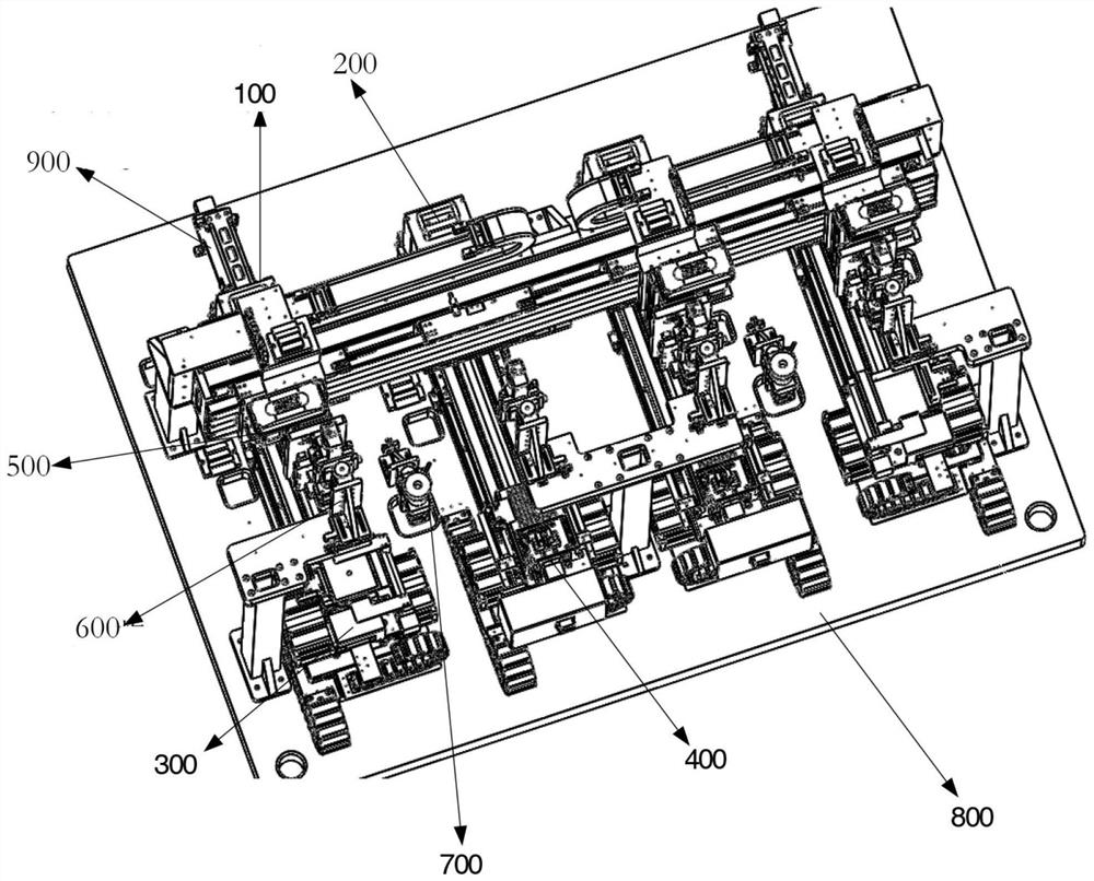
[0041] The technical solution of the present invention and its outstanding advantages are described in detail below with reference to the accompanying drawings. In some embodiments, since the device is a left-right symmetrical mechanism, in order to simplify the description, the following embodiments of the present invention mainly introduce the mechanism of the left part of the device, and the structure of the right part is symmetrical or similar to the device.

[0042] figure 1 The main body configuration of the embodiment of the present invention is exemplarily depicted. Generally speaking, the lens assembly equipment mainly includes a frame structure 800 (such as a rigid frame structure, which can be metal / alloy, hard insulating material, etc.) , lower flexibility), and the lens discharge push rod structure 900, the lens bin lifting structure 100, the mirror base bin lifting structure 200, the lens transport structure 300, the mirror base transport structure 400, which ar...


PUM


Abstract

The invention provides a positioning assembly method for camera lens assembly equipment. The camera lens assembly equipment comprises a lens transportation structure, a lens base transportation structure and a beam type assembly structure which are arranged on a framework structure with a standard plane in parallel as well as a control module, wherein the lens base transportation structure provides an assembly platform for assembling the lens and the lens base; and the control module is separately electrically connected to the lens transportation structure, the lens base transportation structure and the beam type assembly structure. The method comprises the following steps: controlling the lens transportation structure for transporting a lens tray to a preset position through the control module for facilitating sucking of the beam type assembly structure, controlling the lens base transportation structure to take out the lens base tray and transport a lens base from a lens base stock bin, controlling the beam type assembly structure to suck the lens from the lens tray transmitted from the lens transportation structure and assemble the lens into the lens base received and fixed by the lens base transportation structure through the control module, and transmitting back the lens into the original lens base stock bin through the lens base transportation structure.

Description

technical field [0001] The present invention mainly provides an automatic lens positioning and assembling method for electronic equipment lenses, in particular, mainly for the assembly and optical precise determination of lenses and mirror holders of electronic equipment (such as intelligent electronic equipment, personal computers, etc.) . Background technique [0002] As the market's performance requirements for electronic equipment lenses gradually increase and the update cycle of electronic equipment continues to shorten, especially the desire to install lenses with better optical performance in more compact electronic equipment, the number of lenses in electronic equipment lenses and Optical performance requirements are also gradually increasing, which in turn makes the assembly requirements for such lenses also increase. [0003] At present, the accuracy of manual assembly can no longer meet the requirements of existing lenses with high pixel and high definition. Sim...

Claims


Application Information

Patent Timeline
Patent Type & Authority Applications(China)
IPC IPC(8): B23P19/00B23P21/00
CPCB23P19/00B23P19/001B23P21/00
Inventor 汪成林
Owner 杭州卓盈智能装备有限公司
Why Eureka
Try Eureka