
Punching clamp for high-temperature nozzle

A punching fixture, high temperature technology, applied in the direction of clamping, manufacturing tools, drilling/drilling equipment, etc., can solve the problems that the drilling position cannot be guaranteed, the drilling slope is unstable, and the drilling position is offset. Achieve good market application value, good processing effect and stable clamping effect

Active Publication Date: 2020-09-04
深圳市阿尓法智慧科技有限公司
View PDF7 Cites 7 Cited by
  • Summary
  • Abstract
  • Description
  • Claims
  • Application Information

AI Technical Summary

Problems solved by technology

[0002] High-temperature nozzles are used in high-temperature dust removal and spraying, combustion furnace ignition nozzles, and fire-fighting and other fields. The requirement of the scene is the decisive factor. It can be seen that the processing of the nozzle on the high temperature nozzle is particularly important, that is, the tilt position of the nozzle on the high temperature nozzle plays a decisive role, and the drilling action of the nozzle is mostly processed by a drilling machine. It is often used for conventional drilling, but when drilling a hole with an inclined angle, it must be adjusted with a jig. At present, the high-temperature nozzle is placed on a simple jig. Adjust the block so that the drilling position of the high-temperature nozzle is located below the drill bit, and then perform the drilling action. However, because the cutting surface of the drill bit is in contact with the inclined surface in this method, it is easy to cause damage to the drill bit itself, and it is easy to cause the drilling position to shift. , eventually making the processed high-temperature nozzle a waste product, and the inclination of the punching hole is also extremely unstable, which cannot guarantee the precise punching position

Method used


Image

  • Punching clamp for high-temperature nozzle
  • Punching clamp for high-temperature nozzle
  • Punching clamp for high-temperature nozzle

Examples


Embodiment 1

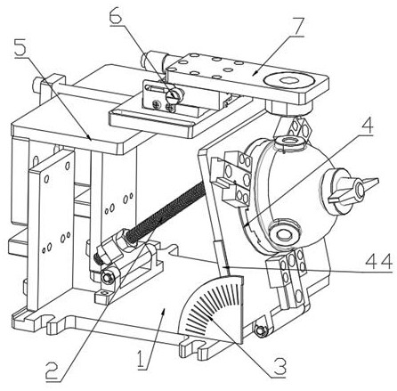
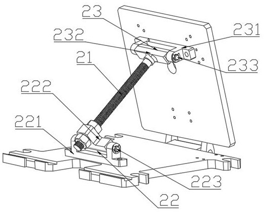
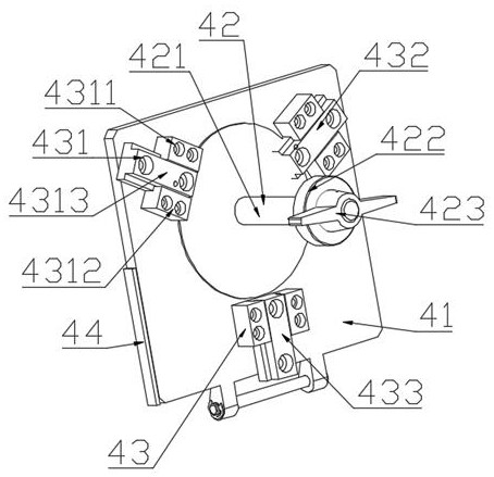
[0032] Such as figure 1 As shown, Embodiment 1 of the present invention: a punching jig for high temperature nozzles, the punching jig for high temperature nozzles is fixed on the drilling machine console, the punching jig for high temperature nozzles includes a support base 1 , an angle adjustment mechanism 2, an angle measurement assembly 3, a clamping mechanism 4, a fixed adjustment mechanism 5, a movable adjustment mechanism 6 and a drill protection assembly 7, the support base 1 is fixed on the drilling machine console, and the angle adjustment mechanism 2 One end is hinged with the left side of the support base 1, the other end of the angle adjustment mechanism 2 is hinged with the upper back side of the clamping mechanism 4, and the bottom of the clamping mechanism 4 is hinged with the right end of the support base 1 The angle measurement assembly 3 is fixed on the right front side of the support base 1, and the inner side of the angle measurement assembly 3 is in conta...


PUM


Abstract

The invention discloses a punching clamp for a high-temperature nozzle. The punching clamp for the high-temperature nozzle comprises a supporting base, an angle adjusting mechanism, an angle measuringassembly, a clamping mechanism, a fixed adjusting mechanism, a movable adjusting mechanism and a drill bit protection assembly, wherein the supporting base is fixed on a drilling machine operating platform, the angle adjusting mechanism is hinged to the supporting base and the clamping mechanism, the bottom of the clamping mechanism is movably connected with the right end of the supporting base,the angle measuring assembly is fixed to the right front side of the supporting base, the fixed adjusting mechanism is vertically fixed to the left end of the supporting base, the movable adjusting mechanism is arranged on the fixed adjusting mechanism, and the drill bit protection assembly is arranged on the movable adjusting mechanism and extends to the position over the clamping mechanism. Thepunching clamp can effectively guarantee a precise punching position, is stable in clamping, reduces the reject ratio, is good in machining effect, and has good market application value.

Description

technical field [0001] The invention relates to the technical field of high-temperature nozzle processing equipment, in particular to a punching jig for high-temperature nozzles. Background technique [0002] High-temperature nozzles are used in high-temperature dust removal and spraying, combustion furnace ignition nozzles, and fire-fighting and other fields. The requirement of the scene is the decisive factor. It can be seen that the processing of the nozzle on the high temperature nozzle is particularly important, that is, the tilt position of the nozzle on the high temperature nozzle plays a decisive role, and the drilling action of the nozzle is mostly processed by a drilling machine. It is often used for conventional drilling, but when drilling a hole with an inclined angle, it must be adjusted with a jig. At present, the high-temperature nozzle is placed on a simple jig. Adjust the block so that the drilling position of the high-temperature nozzle is located below th...

Claims


Application Information

Patent Timeline
Patent Type & Authority Applications(China)
IPC IPC(8): B23Q3/06B23Q3/04B23B49/02
CPCB23B49/02B23Q3/04B23Q3/062
Inventor 陈巧妹
Owner 深圳市阿尓法智慧科技有限公司
Learn More