Brake disc loading and unloading clamp capable of automatically changing spacing

A variable pitch and brake disc technology, applied in the field of brake disc loading and unloading fixtures, can solve problems such as low production efficiency, potential safety hazards, and increased automation needs, and achieve the effects of improving grasping efficiency, ensuring product quality, and improving production efficiency

Inactive Publication Date: 2020-09-04
龙口市埃迪克自动化设备有限公司
View PDF0 Cites 1 Cited by
  • Summary
  • Abstract
  • Description
  • Claims
  • Application Information

AI Technical Summary

Problems solved by technology

[0002] With the vigorous development of the automobile industry, the requirements for auto parts are increasing day by day. As an important part of automobiles, the market demand for brake discs is increasing. The target production capacity requirements for intelligent manufacturing of brake discs are increasing. The demand is increasing. Due to the large variety of brake disc sizes and the automatic loading and unloading fixtures for multi-type disc processing parts, the type change in the production process requires manual adjustment and replacement of the automatic production fixture of the brake disc. There are many safety hazards in manual changeover. The safety of workers cannot be guaranteed, and at the same time, the accuracy of the changeover cannot be guaranteed, resulting in low production efficiency. Therefore, the demand for automatic variable pitch fixtures is a rigid demand. A fixture that can efficiently solve the problem of automatic loading and unloading changeovers is hereby developed.

Method used


Image

  • Brake disc loading and unloading clamp capable of automatically changing spacing
  • Brake disc loading and unloading clamp capable of automatically changing spacing
  • Brake disc loading and unloading clamp capable of automatically changing spacing

Examples


Embodiment Construction

[0018] The principles and features of the present invention are described below in conjunction with the accompanying drawings, and the examples given are only used to explain the present invention, and are not intended to limit the scope of the present invention.

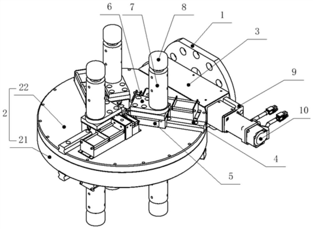
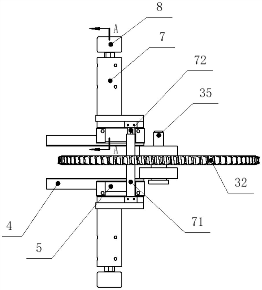
[0019] An automatic variable pitch brake disc loading and unloading fixture, comprising a frame body 2, a transmission device 3 that is movably connected inside the frame body 2, and the transmission device 3 is provided with at least three drive claws 7 that are movably connected, and the drive claw 7 is connected to the frame The body 2 is movably connected, and the free end of the driving claw 7 is provided with an electromagnet 8 .

[0020] The frame body 2 includes a fixed frame 21, and fixedly connected fixed plates 22 are arranged on the upper and lower sides of the fixed frame 21.

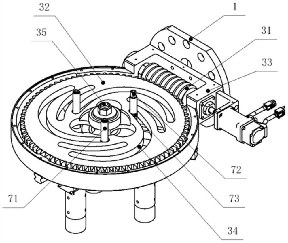
[0021] The transmission device 3 includes a worm wheel 32 installed in the frame body 2, the worm wheel 32 is movably connected...


PUM


Abstract

The invention relates to a brake disc loading and unloading clamp capable of automatically changing spacing, and belongs to the technical field of brake disc loading and unloading clamps. The brake disc loading and unloading clamp comprises a frame body, wherein a transmission device which is movably connected is arranged inside the frame body; the transmission device is provided with at least three drive claws which are movably connected; the drive claws are movably connected to the frame body; the free ends of the drive claws are provided with electromagnets; motors drive the drive claws tomove back and forth between the edge of the frame body and the circle center; a turbine is provided with a cam track slot; center distances of the drive claws can be changed by rotating the turbine, so that manual automatic model replacing can be effectively replaced, and multiple potential safety hazards in manual model replacing are avoided; through self-locking characteristics of a turbine anda worm, the positions of the drive claws are fixed, spacing is not changed along with gripping stress, product quality is guaranteed by precise model replacing, and production efficiency is improved;and the drive claws on upper and lower surfaces of the frame body can turn over up and down by clamping a connecting plate through a mechanical hand, so that dual-station changing can be realized, andgripping efficiency can be effectively improved.

Description

technical field [0001] The invention relates to an automatic variable-spacing clamp for loading and unloading brake discs, which is aimed at grabbing brake discs for loading and unloading, and in particular relates to a clamp which belongs to the technical field of clamps for loading and unloading brake discs. Background technique [0002] With the vigorous development of the automobile industry, the requirements for auto parts are increasing day by day. As an important part of automobiles, the market demand for brake discs is increasing. The target production capacity requirements for intelligent manufacturing of brake discs are increasing. The demand is increasing. Due to the large variety of brake disc sizes and the automatic loading and unloading fixtures for multi-type disc processing parts, the type change in the production process requires manual adjustment and replacement of the automatic production fixture of the brake disc. There are many safety hazards in manual ch...

Claims


Application Information

Patent Timeline
Patent Type & Authority Applications(China)
IPC IPC(8): B65G47/90
CPCB65G47/90B65G2207/08
Inventor 杨传标
Owner 龙口市埃迪克自动化设备有限公司
Why Eureka
Try Eureka