Building formwork reinforcing device

A formwork reinforcement and construction technology, which is applied in the field of formwork reinforcement equipment, can solve the problems of uneven force application of formwork and reinforcement plates, and achieve the effects of uniform force application, simple and orderly reinforcement process, and avoidance of slurry leakage.

Active Publication Date: 2020-09-04
浙江润泰建设有限公司
View PDF8 Cites 2 Cited by
  • Summary
  • Abstract
  • Description
  • Claims
  • Application Information

AI Technical Summary

Problems solved by technology

[0004] The purpose of the present invention is to solve the disadvantages of the building formwork reinforcement device in the prior art that run out of the fixed formwork due to uneven force applied to the reinforcement plate, and propose a construction formwork reinforcement device

Method used


Image

  • Building formwork reinforcing device
  • Building formwork reinforcing device
  • Building formwork reinforcing device

Examples


Embodiment 1

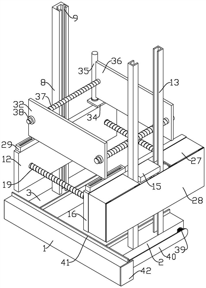
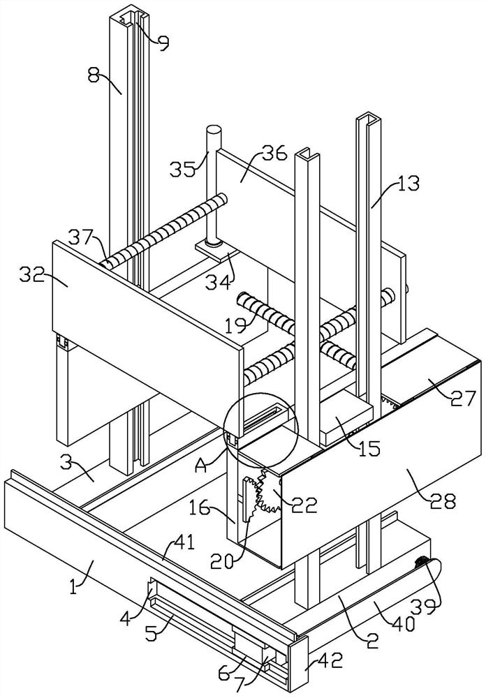
[0027] refer to Figure 1-8, a formwork reinforcement device for construction, comprising a base 1, a front base 2 and a rear base 3, one end of the rear base 3 is fixedly mounted on the base 1, a groove 4 is opened on one side of the base 1, and the upper and lower ends of the groove 4 Both are provided with a first card slot 5, and a first card block 6 is slidably arranged in the first card slot 5, and a block 7 is slidably arranged in the slot 4, and the upper and lower ends of the block 7 are respectively fixedly connected with the first card block 6, and the front One end of the side base 2 is fixedly connected to the block 7, and the top of the rear base 3 is fixedly equipped with a rear side slide rail 8, and both sides of the rear side slide rail 8 are provided with a second card slot 9, and the second card slot 9 is slidingly arranged There is a second block 10, and a first slider 11 is slidably arranged in the rear side slide rail 8, and both sides of the first slide...

Embodiment 2

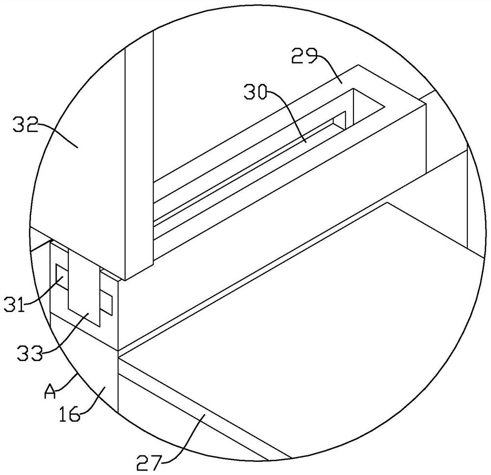
[0032] Since the working environment of the device is mostly on the construction site, it will inevitably be affected by dust and the mud inside the formwork. A series of transmission structures in Example 1, such as the tooth disc and the surface of the screw rod, when there are mud dust and other pollutants, will be affected. Cause transmission to be blocked, not smooth or even stuck by solidified mud, refer to Figure 1-8 , as another preferred embodiment of the present invention, the difference from Embodiment 1 is that two oppositely arranged U-shaped frames 27 are provided on one side of the front side pressing plate 16, and a gap is provided between the two U-shaped frames 27, and The two front side slide rails 13 are located between the two U-shaped frames 27, the upper end of one side of the U-shaped frame 27 is hinged with a cover plate 28, and the two first toothed discs 20 and the fourth toothed disc 25 are located In the space formed by side pressure plate 16 and ...


PUM


Abstract

The invention relates to the technical field of formwork reinforcing equipment, and in particular relates to a building formwork reinforcing device. The device comprises a base, a front side base anda rear side base, wherein a rear side pressing plate is arranged at the top end of the rear side base, a front side pressing plate is arranged at the top end of the front side base, bearing sleeves are fixedly mounted at two ends of one side of the front side pressing plate correspondingly, first threaded sleeves are fixedly mounted in the bearing sleeves correspondingly, and first fluted discs are fixedly mounted outside the first threaded sleeves on two sides. By arranging the rear side pressing plate, the front side pressing plate, the bearing sleeves, the first threaded sleeves, first screw rods, the first fluted discs, first rotating shafts, a second fluted disc, a third fluted disc, a second rotating shaft, a fourth fluted disc and a grab handle which are matched with one another, the first threaded sleeves on the two sides are the same in rotating speed and consistent in rotating direction in the rotating process, then the stress of the internal formwork is uniform, and thus theproblems of slurry leakage, formwork deviation, formwork explosion and the like caused by large errors in manual assembly and splicing of reinforcing plates are avoided.

Description

technical field [0001] The invention relates to the technical field of formwork reinforcement equipment, in particular to a formwork reinforcement device for construction. Background technique [0002] The building formwork is a temporary support structure, which is manufactured according to the design requirements, so that the concrete structure and components are formed according to the specified position and geometric size, maintain their correct position, and bear the self-weight of the building formwork and the external load acting on it. Among them, in order to clamp and fix the building formwork conveniently, people often use a device, which is a building formwork reinforcement device. If the quality of the formwork fixing is not good, it will cause serious consequences such as grout leakage or even wall tilting and collapse. The construction quality and construction schedule have been seriously affected. [0003] The existing square column formwork is reinforced by ...

Claims


Application Information

Patent Timeline
Patent Type & Authority Applications(China)
IPC IPC(8): E04G13/02E04G17/00
CPCE04G13/02E04G17/00
Inventor 吴益安赖世清
Owner 浙江润泰建设有限公司
Why Eureka
Try Eureka