Supercharge Your Innovation With Domain-Expert AI Agents!

Variable stiffness vibration damping device

一种减振装置、变刚度的技术,应用在减振器、动力装置、喷气推进装置等方向,能够解决阻尼特性降低、难具有期望的特性、减振装置的刚度和阻尼特性调节范围窄等问题

Active Publication Date: 2020-09-04
HONDA MOTOR CO LTD
View PDF9 Cites 0 Cited by
  • Summary
  • Abstract
  • Description
  • Claims
  • Application Information

AI Technical Summary

Problems solved by technology

Therefore, the adjustment range of the stiffness and damping characteristics of the entire vibration damping device is narrow, so it is difficult to have desired characteristics at any frequency
For example, it is difficult to adjust at multiple frequencies so that when vibrations around 10 Hz that affect the ride comfort of the car are generated, the damping characteristics are enhanced, and when vibrations around 130 Hz that affect the muffled sound of the engine are generated, Reduced damping characteristics
[0007] On the other hand, in ACM, the mechanism for directly inputting external energy into it becomes complicated

Method used


Image

  • Variable stiffness vibration damping device
  • Variable stiffness vibration damping device
  • Variable stiffness vibration damping device

Examples


no. 1 approach 》

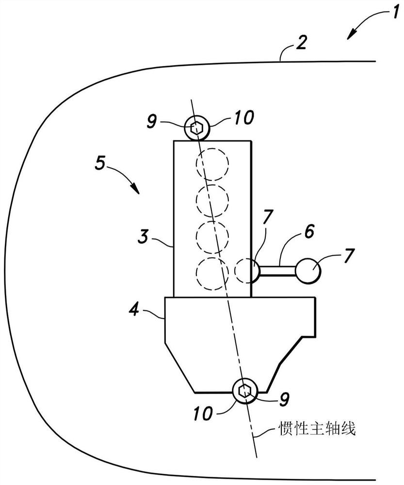
[0040] First, refer to Figure 1 to Figure 10B The first embodiment of the present invention is described. Such as figure 1 As shown, the engine 3 is arranged laterally in the front part of the body 2 of the car 1 (vehicle). The transmission 4 is provided integrally with the engine 3, and the power plant 5 is composed of the engine 3, the transmission 4, and the like. The power plant 5 is supported by the vehicle body 2 via a pair of engine mounts (side mounts and lateral mounts) and a torque rod 6. The pair of engine supports is composed of a pair of variable stiffness damping devices 10 (hereinafter referred to as "damping devices 10").

[0041] The vibration damping device 10 receives the main load (own weight) of the power unit 5. Each damping device 10 is located on the main axis of inertia of the entire power plant 5 and fixed to the vehicle body 2. On the other hand, the torque rod 6 is connected to the engine 3 via a rubber bush 7 on one longitudinal end thereof, and i...

no. 2 approach 》

[0076] Next, refer to Picture 11 The second embodiment of the present invention is described. Elements of the second embodiment that are the same as or similar to those of the first embodiment are given the same reference numerals as those of the first embodiment, and the description of the second embodiment that may repeat the description of the first embodiment is omitted. In the second embodiment, the configuration around the coil 26 is different from that in the first embodiment. Hereinafter, the second embodiment will be specifically described.

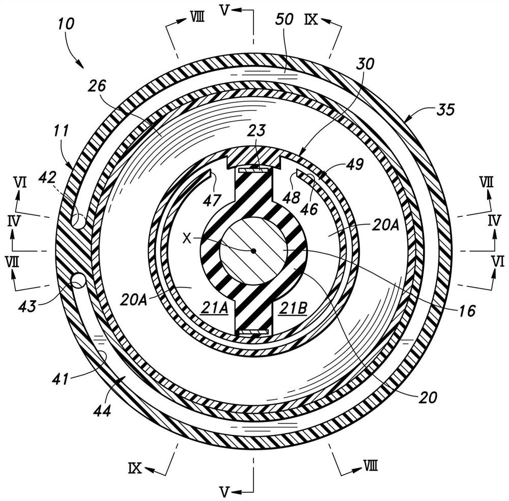
[0077] Picture 11 Is the sum of the vibration damping device 10 according to this embodiment Figure 4 Sectional view in the corresponding section. Such as Picture 11 As shown, the first support member 11 includes an annular inner yoke 25 and an annular outer yoke 27. The inner yoke 25 is provided in the inner peripheral portion of the first support member 11. A pair of coils 26 (26A, 26B) are coaxially wound around the outer ...


PUM


Abstract

A variable stiffness vibration damping device includes a first support member, a second support member, a main elastic member, a diaphragm, a partition elastic member, a first communication passage, acoil, a yoke, and a magnetic fluid. The first communication passage is provided in one of the first support member and the second support member such that a first liquid chamber and a second liquid chamber communicate with each other via the first communication passage. The first communication passage includes a first circumferential passage. The coil is wound coaxially with the one of the firstsupport member and the second support member. The yoke is included in the one of the first support member and the second support member and forms a first magnetic gap overlapping at least partially with the first circumferential passage.

Description

Technical field [0001] The invention relates to a variable stiffness vibration damping device filled with a magnetic fluid. Background technique [0002] A known liquid-filled vibration damping device for a liquid-filled engine mount or the like includes a first mounting member mounted on the vibration source side, a second mounting member mounted on the vibration receiving side, and made of an elastic material such as rubber. An insulator (vibration-proof rubber) interposed between the first mounting member and the second mounting member, a liquid chamber with a wall partially defined by the insulator, partitioning the inside of the liquid chamber into a main liquid chamber and an auxiliary liquid chamber A member, a diaphragm closing the auxiliary liquid chamber, and a resonance hole connecting the main liquid chamber and the auxiliary liquid chamber (for example, JP2005-98312A and JP2004-263783A). [0003] When low-amplitude vibration is generated, the engine mount is required ...

Claims


Application Information

Patent Timeline
Patent Type & Authority Applications(China)
IPC IPC(8): F16F13/30F16F13/10
CPCF16F13/305F16F13/10F16F2224/045F16F2228/066B60K5/1216B60K5/1225B60K5/1241B60K5/1283B60K5/1208
Inventor 伊藤优步井上敏郎
Owner HONDA MOTOR CO LTD
Features
  • R&D
  • Intellectual Property
  • Life Sciences
  • Materials
  • Tech Scout
  • Unparalleled Data Quality
  • Higher Quality Content
  • 60% Fewer Hallucinations
Learn More