Laser measuring device for measuring reservoir water level and measuring method thereof

A technology of reservoir water level and laser measurement, which is used in measurement devices, lubrication indicating devices, liquid/fluid solid measurement, etc. The effect of saving manpower, improving accuracy and simple structure

Pending Publication Date: 2020-09-04
HUBEI QINGJIANG HYDROPOWER DEV
View PDF3 Cites 7 Cited by
  • Summary
  • Abstract
  • Description
  • Claims
  • Application Information

AI Technical Summary

Problems solved by technology

[0006] The main purpose of the present invention is to provide a laser measuring device for measuring the water level of a reservoir and its measuring method, so as to solve the problem that the infrared rays emitted by the infrared range finder will penetrate the water body when the infrared range finder measures the water level, resulting in inaccurate measurement of the water level, When there are a lot of floating objects on the surface of the reservoir water body, it will affect the accuracy of the measurement and the water level data needs to be counted manually, which is not only time-consuming and labor-intensive, but also prone to errors

Method used


Image

  • Laser measuring device for measuring reservoir water level and measuring method thereof
  • Laser measuring device for measuring reservoir water level and measuring method thereof
  • Laser measuring device for measuring reservoir water level and measuring method thereof

Examples


Embodiment 1

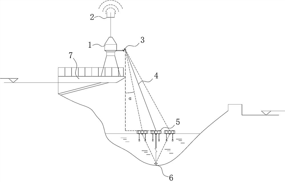
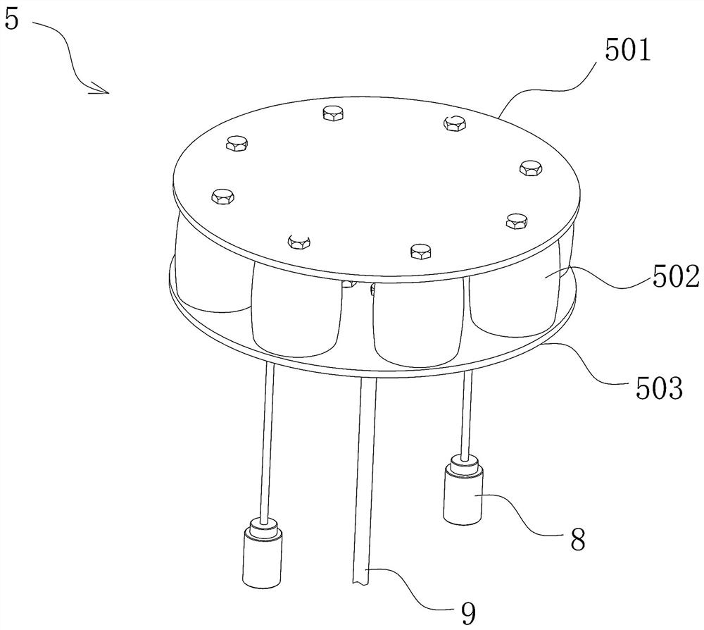
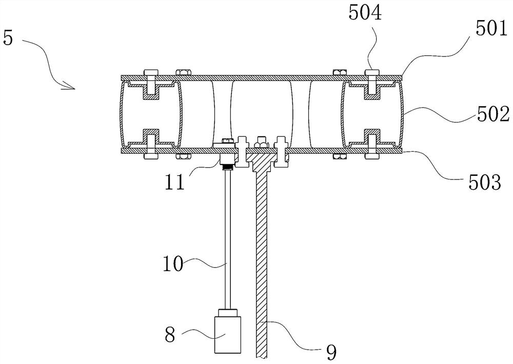
[0042] Such as Figure 1~9 As shown, a laser measuring device for measuring the water level of a reservoir includes an infrared ranging tracking head 3 and a water level gauge target plate 5. The infrared ranging tracking head 3 is arranged on the control tower 1, and the outer ranging tracking head 3 includes a tracking The camera 301 is provided with an infrared distance measuring head 302 above the tracking camera 301, and the tracking camera 301 is hinged with the outer casing 305, and the lower part of the outer casing 305 is connected with the fixed plate 14 in rotation, and the outer casing 305 is provided with a first driving device 15 and a second driving device. Device 16, the first driving device 15 drives the outer casing 305 to rotate, the second driving device 16 drives the tracking camera 301 to swing up and down, the water level gauge target plate 5 is arranged on the water surface of the reservoir, and the water level gauge target plate 5 is fixed by the fixed ...

Embodiment 2

[0053] Further illustrate in conjunction with embodiment 1, as Figure 1~9 shown;

[0054] The water level gauge target disc 5 is painted yellow or red as a whole. The reflection effect of yellow and red is better, and it is also convenient for the tracking camera 301 to track the yellow or red target disk.

[0055] Put the water level gauge target plate 5 into the reservoir, and fix the position of the water level gauge target plate 5 by fixing the anchor 6.

[0056] A counterweight 8 is installed below the water level gauge target disc 5 to prevent the wind from blowing the target disc or water from fluctuating.

[0057] Install the infrared ranging tracking head 3 on the control tower 1 on the detection platform 7, and set the internal tracking camera 301 tracking target of the infrared ranging tracking head 3 to be yellow or red.

[0058] The tracking camera 301 controls the first driving device 15 and the second driving device 16 to lock the position of the target disk...


PUM


Abstract

The invention provides a laser measuring device for measuring the water level of a reservoir and a measuring method thereof. The device comprises an infrared distance measurement tracking head and a water level indicator target disc, wherein the infrared distance measurement tracking head is arranged on the control tower; the outer distance measurement tracking head comprises a tracking camera; aninfrared distance measuring head is arranged above the tracking camera; the tracking camera is hinged with the outer shell; the lower part of the shell is rotationally connected with a fixed plate; afirst driving device and a second driving device are arranged in the outer shell; the first driving device drives the outer shell to rotate; the second driving device drives the tracking camera to swing up and down; the water level indicator target disc is arranged on the water surface of the reservoir; the water level indicator target disc is fixed through a fixing anchor; a tracking camera in the infrared distance measuring tracking head is used for tracking the position of the water level indicator target disc, wherein the infrared distance measuring head is used for shooting on the waterlevel indicator target disc to measure the water level. By means of the device, a worker can master the water level of a reservoir in real time, the worker does not need to go to the site to read data, manpower is saved, and the water level measuring accuracy of the device is improved.

Description

technical field [0001] The invention relates to the field of reservoir water level measurement, in particular to a laser measuring device for measuring the water level of a reservoir and a measurement method thereof. Background technique [0002] Water level measurement is an important measurement item in hydrological survey. At present, water level measurement is usually carried out by using a vertically observed water level gauge. The water level gauge is fixedly installed directly above the river through the water level gauge bracket, and the water level measurement is realized by measuring the distance between the water level gauge and the water surface through the distance measuring probe of the water level gauge. Since the water level gauge is installed directly above the river, and the water level gauge support is fixed, if the river bed rises, the water level gauge support is easily washed away by the flood, a large amount of silt is accumulated, or it is submerged,...

Claims


Application Information

Patent Timeline
Patent Type & Authority Applications(China)
IPC IPC(8): G01F23/292
CPCG01F23/292
Inventor 董峰陈剑祝迪张晋境张言孔祥宇
Owner HUBEI QINGJIANG HYDROPOWER DEV
Why Eureka
Try Eureka