Reading circuit and calibration method thereof

A technology of readout circuit and calibration method, applied in the field of uncooled infrared focal plane array, can solve the problems of output offset, large influence of temperature change, inability to compensate for macro offset temperature drift, etc., to achieve adjustable output offset and little effect of temperature change Effect

Active Publication Date: 2020-09-04
北京安酷智芯科技有限公司
View PDF5 Cites 5 Cited by
  • Summary
  • Abstract
  • Description
  • Claims
  • Application Information

AI Technical Summary

Problems solved by technology

However, due to process defects, the pixels, mirror pixels, blind pixels, and mirror blind pixels of the mirror architecture cannot be completely matched, especially when the pixels are irradiated by hotter or colder objects, the degree of mismatch is more obvious
When the mirror bias structure is mismatched, the output may be offset; if there is a mismatch in the temperature coefficient of the resistor substrate, the offset may cause temperature drift; the mismatch will also cause a decrease in the common-mode rejection ratio, and introduce greater power supply and bias noise. ; Offset and offset temperature drift will affect the dynamic range of imaging, so macroscopic correction is required
There are three methods for output offset in the prior art: one is to use the voltage adjustment method, which only corrects the output offset and cannot compensate for the drop in common-mode rejection ratio caused by image mismatch; the other is the traditional resistance compensation adjustment method , the use of series resistors to adjust the offset is only effective at a single substrate temperature, it cannot compensate the macro offset temperature drift, and may increase the macro offset temperature drift; the third traditional TCR compensation adjustment method, using series resistors to adjust TCR, needs to be listed The compensation of positive and negative temperature drift can only be achieved by connecting low TCR resistors in series, which increases column-level non-uniformity, and TCR compensation resistors may introduce additional fixed offsets, making the calibration process more complicated
It can be seen that in the prior art, not only the correction of macroscopic offset and macroscopic offset temperature drift cannot be realized at the same time, but also the quality of readout and the stability of the circuit are affected due to the improper use of the correction method; Changes have a greater impact

Method used


Image

  • Reading circuit and calibration method thereof
  • Reading circuit and calibration method thereof
  • Reading circuit and calibration method thereof

Examples


Embodiment Construction

[0035] The following will clearly and completely describe the technical solutions in the embodiments of the present invention with reference to the accompanying drawings in the embodiments of the present invention. Obviously, the described embodiments are only some, not all, embodiments of the present invention. Based on the embodiments of the present invention, all other embodiments obtained by persons of ordinary skill in the art without making creative efforts belong to the protection scope of the present invention.

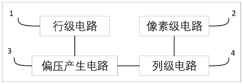
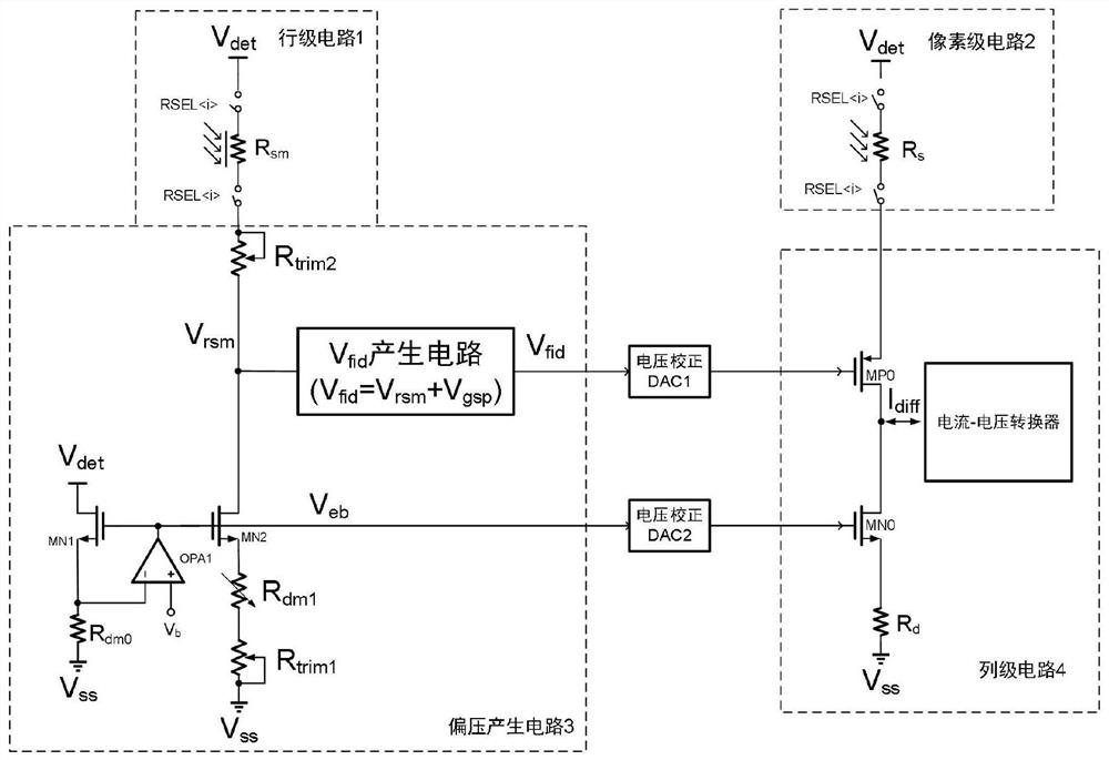
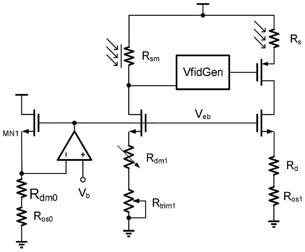
[0036] The mirror bias architecture is commonly used in the readout circuit of the uncooled infrared focal plane detector. The bias voltage is generated by using the mirror pixel based on shading to realize the suppression of the influence on the substrate temperature, common mode voltage and self-heating effect. However, due to defects in the process, the pixels, mirror pixels, blind pixels, and mirror blind pixels of the mirror architecture cannot be complete...


PUM


Abstract

The invention discloses a reading circuit and a calibration method thereof, and relates to the technical field of uncooled infrared focal plane arrays. The reading circuit comprises a row-level circuit, a pixel-level circuit, a bias voltage generation circuit and a column-level circuit. The output end of the row-level circuit is connected with the input end of the bias voltage generation circuit;the bias generation circuit at least comprises a low TCR resistor and a blind resistor; a first bias voltage and a second bias voltage are output to the column-level circuit according to the output ofthe row-level circuit and the input constant voltage; and the column-level circuit is also connected with the pixel-level circuit, obtains two paths of current according to the first bias voltage andthe second bias voltage, converts the generated differential current and outputs the converted differential current as output voltage. By adjusting the low TCR resistor and the blind resistor, correction of the reading circuit is realized.

Description

technical field [0001] The invention relates to the technical field of uncooled infrared focal plane arrays, in particular to a readout circuit and a calibration method thereof. Background technique [0002] As one of the key components of the uncooled infrared focal plane array (IRFPA), the readout circuit's main function is to preprocess the weak signals sensed by the infrared detector (such as integration, amplification, filtering, sampling / holding, etc.) and the array signal parallel / serial conversion. [0003] The mirror bias architecture is commonly used in the readout circuit of the uncooled infrared focal plane detector. The bias voltage is generated by using the mirror pixel based on shading to realize the suppression of the influence on the substrate temperature, common mode voltage and self-heating effect. However, due to defects in the process, the pixels, mirror pixels, blind pixels, and mirror blind pixels of the mirror architecture cannot be completely matche...

Claims


Application Information

Patent Timeline
IPC IPC(8): G01J5/10G01J5/00
CPCG01J5/10G01J5/00G01J5/80
Inventor 刘大河施薛优陈光毅李克之
Owner 北京安酷智芯科技有限公司
Why Eureka
Try Eureka